
To a robot builder, nothing is more satisfying than seeing their creation perform well by responding appropriately to its real world surroundings. To achieve this, a number of sensors are required to give a robot cognizance. Even the simplest of robots must be able to move about the world with little or no difficulty. To this end, this article presents a survey of the technologies, tools, and techniques of robotic cognizance.
Bumper Switches
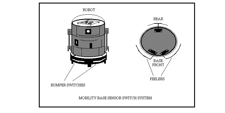
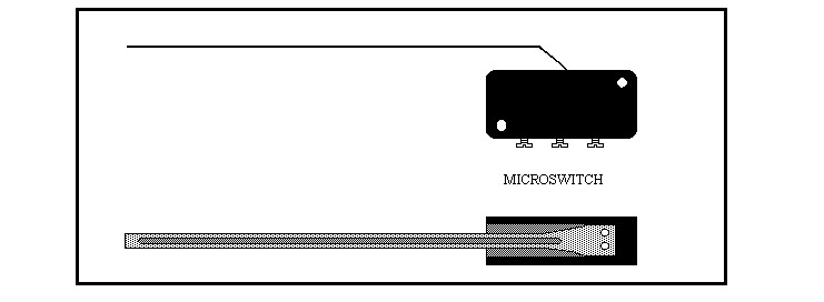
Small robots—and even some of the more sophisticated types—use switches near the ground to detect objects and avoid them. Micro-switches are best for this application and some of the larger varieties feature long built-in feelers. Secured to the mobility base, the feelers are bent to conform to the shape of the robot. One switch is secured to the left of the mobility base, one to the left, and in some sophisticated designs, one in the rear. Despite the fact that this system is very basic, even advanced robots use it as a backup for light or sonic distance detecting systems.
The switching system works only if an interfacing circuit is provided because as soon as the switch is released, the direction will turn back and the robot will be caught in an unending back and forth motion.
The circuit diagram shows the micro-switch triggering a 555 timer IC. When the switch is triggered the IC holds the motor direction relay on for about two seconds. This gives the backup time to pull away, even though the switch has already reset. Resistor R3 adjusts the backup time to synchronize the action with other system parameters. Capacitor C1 may need to be replaced by a smaller value if the operating voltage is more than 9 volts.
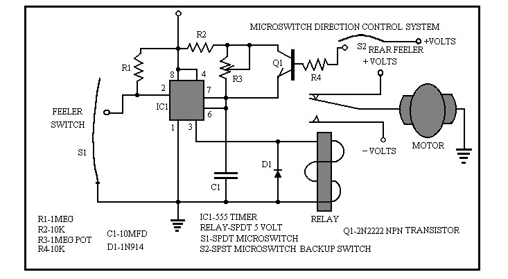
The relay should be chosen to match the system operating voltage. If a rear switch is used, it should set both motors to forward motion by canceling the forward time set by potentiometer R3.
Stability Switches
One very important element that all roboticists should be aware of is ground continuity. I learned this lesson when my sentry robot took a tumble down a flight of stairs when someone left a stair well wide open. If I had installed a ground continuity switch, I would have avoided spending many hours at the repair bench. A rolling ball device is better suited to maneuver turns, as you can see in the illustration below.
Tall robots are vulnerable to being toppled by tables or other obstacles. To guard against this, four mercury switches mounted to a circuit board at an angle (see illustration, below) will detect an alteration in the upright position. Make sure that the angle of the mercury switches is steep enough to avoid triggering at every little bump. A support board below the circuit board provides support to maintain the angle over time.
For advanced designs, the mercury switches can provide a trigger to devices that correct the displacement of the robot. For less sophisticated designs, an alarm can be activated to let you know your robot is in trouble.
Robot Eyes
Another way to keep your robot from bumping into everything is to give it eyes. The two primary components used in electronic eyes are phototransistors and cadmium sulfide photocells. Both are sensitive to light, however, the transistor is faster acting, which will probably not be a factor in your design.
Cadmium cells are less expensive, so if you want to set up an array, like the one illustrated below, you won’t need a bank loan.
We see in the robot eye circuit a cadmium cell connected to a 555 timer. As a robot surveys the territory in front, all sorts of light conditions and reflections are encountered. As the robot approaches a wall the angles of direct and reflected light are cut off as less and less light is detected until a back up pulse is generated. Robot eyes are better described as dark detectors.
A small tube around the detection device limits the effect of ambient light on the circuit. In the schematic, sensitivity to light is controlled by trim-pot R1 and should be adjusted to achieve the desired results on your robot. Potentiometer R5 determines the pulse width of the 555 timer and should be set to provide the proper step signal for your robot. Resistor R6 serves to limit the output current.
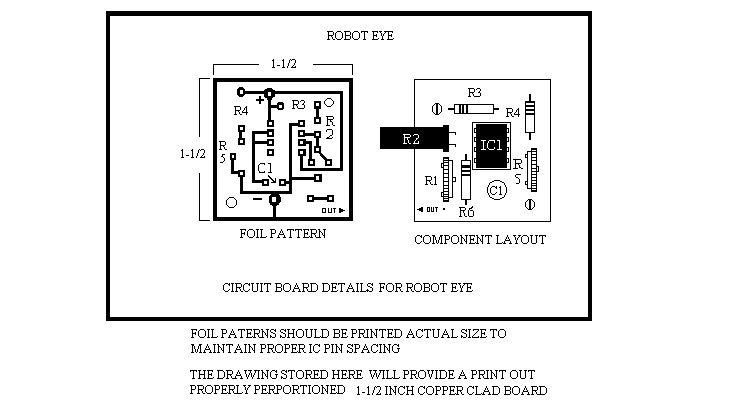
Different amounts of light may strike the surface of the cadmium cell with no effect. When a preset degree of darkness is detected, the 555 timer generates a step pulse. The duration of this pulse is adjustable to accommodate a wide variety of computer situations.
Robot Ears
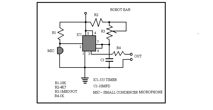
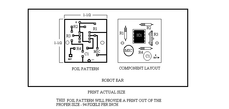
Sound can also be used to trigger response from your robot. In the circuit we see a condenser microphone mounted on the board. Resistor R1 will make the circuit sensitive to only loud sounds, so if you need something more sensitive, increase the value of R1 or add a 100K trimmer potentiometer to adjust sensitivity. Resistor R4 must be included to limit the current from the timer. Circuitry for the ear is simple enough and a basic stop-what-you-are-doing on-off response is all that you can achieve. This is justification enough for including it in your robot, especially if your robot is a sentry listening for sounds of burglars.
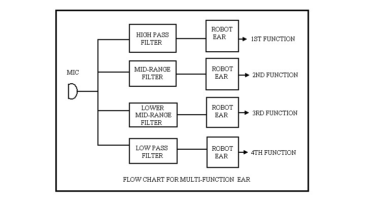
With the use of bandpass filters, a degree of sound discrimination can be achieved. A flow chart is provided above to show how this is accomplished. Each range will trigger a different function, so this type of robot should be operated in a controlled environment with a specific sound agenda, otherwise, your robot may act like a paranoid schizophrenic.
With voice recognition circuits, more advanced responses can be achieved. Even ultrasonic programming has been achieved by using the sonic range finders in old Polaroid cameras.
555 Timer
The use of the 555 timer in most of the circuits in this article is due to the incredible versatility of this device. It can be triggered by just about any device there is and only requires a brief needle pulse to engage it. Output from the timer can be equal to the input pulse or can be set to produce a step pulse adjustable to any length of time necessary for a robot to perform any function. In addition, the timer will operate with a supply voltage of as low as 3 volts to as much as 18 volts. The output of the 555 is full power, so a current limiting resistor is absolutely necessary. It can be said that for interfacing robotic components, the 555 timer has no match.
Hand Control
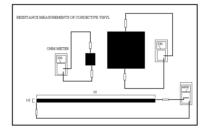
Not all cognizance circuits involve robot mobility. Head, as well as hand and arm movement, require precise control. Sophisticated robotic hands may use conductive vinyl to sense the pressure needed to secure a delicate sample. Conductive vinyl looks and feels just like the vinyl you find on furniture. The only difference is, conductive vinyl conducts electricity. It acts like a resistor with a value of 330 ohms per square. Not per square inch, but per square, no mater what size the square. Increasing the length of a piece of vinyl will increase the resistance to make it more suitable as a voltage divider.
Operation
A triangular piece of conductive vinyl serves as a voltage divider and placed near a sensor plate.
When a sample is grasped the pressure displaces the vinyl and makes contact somewhere along the vinyl strip with the sensor plate. This voltage level is sampled and as long as it stays the same, the grip of the hand will also stay the same. If the voltage decreases, a signal is sent to the motor box and the fingers grip is tightened only until the voltage stops changing.
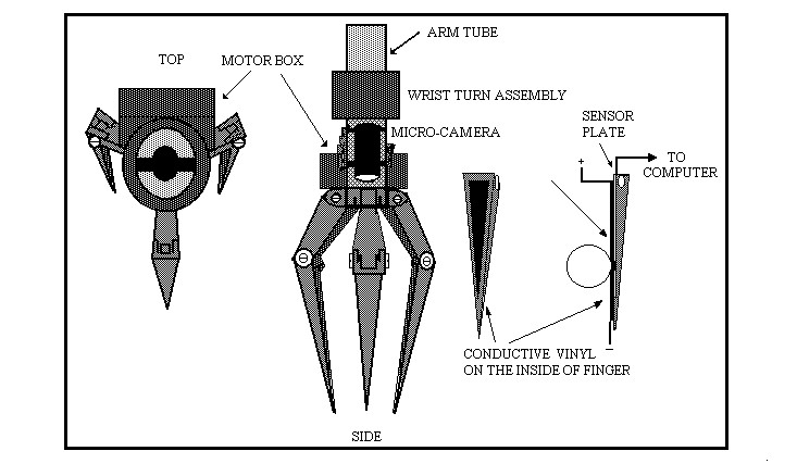
In the hand illustration, the motor box, using small gears, can open and close the lower fingers and widen the grip by spreading the upper fingers. The wrist-turn assembly can rotate the fingers 356 degrees. Sharp pointed fingers enable the hand to dig the ground for hidden samples and a micro-camera and light source, mounted in the arm tube, give the controller a perfect view of the collected sample.
Conductive Rubber
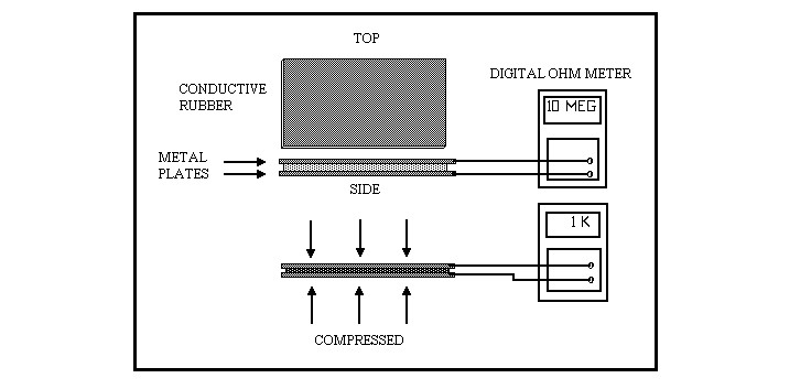
Conductive rubber is another substance that is making an appearance as a potential sensor element for use in robotics. It is made by adding conductive particles to the liquid rubber in the first stages of processing. When the rubber is compressed, the conducting particles become compacted, and a more conductive state is achieved. It comes in a wide variety of densities that are suited to pressure activating situations from as low as 30 pounds to thousands of pounds, the latter being a very popular method of weighing trucks at stations on our nations highways.
Programming
Waking robots can use conductive rubber to indicate contact with the ground, enabling them to more accurately maneuver over rough terrain. Large industrial robots, like those used in welding cars, use elaborate programming to control every movement, but they also need devices to enable them to evaluate their work and avoid accidents.
Conclusion
No matter what kind of robot you build, cognizance will be a major factor in how well it functions. Whether you design small insect-like robots, or you work on large industrial robots, they must be “aware.”
