

Modulation is a technique that changes the characteristics of the carrier frequency in accordance to the input signal [1, 2]. Figure 1.1 shows the conceptual block diagram of a modern wireless communication system. As shown in the figure, modulation is performed at the transmit side and demodulation is performed at the receive side. This is the final stage of any radio communication system. The preceding two stages have been discussed elaborately in my previous book in this series [3, 4].

Figure 1. Block diagram of a modern full-duplex communication system.
The output signal of the modulator, referred to as the modulated signal, is fed into the antenna for propagation. The antenna is a reciprocal device that transmits and receives the modulated carrier frequency. The size of the antenna depends on the wavelength (λ) of the sinusoidal wave where, λ = c/f, meter, c = velocity of light = 3×10⁸ m/s, f = Frequency of the sinusoidal wave, also known as “Carrier Frequency.” Therefore, a carrier frequency much higher than the input signal is required to keep the size of the antenna at an acceptable limit. For these reasons, a high frequency carrier signal is used in the modulation process. In this process, the low frequency input signal changes the characteristics of the high frequency carrier in a certain manner, depending on the modulation technique. Furthermore, as the size and speed of digital data networks continue to expand, bandwidth efficiency becomes increasingly important. This is especially true for broadband communication, where the digital signal processing is done keeping in mind the available bandwidth resources.
Hence, modulation is a very important step in the transmission of information. The information can be either analog or digital, where the carrier is a high frequency sinusoidal waveform. As stated earlier, the input signal (analog or digital) changes the characteristics of the carrier waveform. There are two basic modulation schemes:
- Modulation by analog signals
- Modulation by digital signals
Modulation by Analog Signals
For analog signals, there are three well known modulation techniques:
- Amplitude Modulation (AM)
- Frequency Modulation (FM)
- Phase Modulation (PM)
Each of these modulation techniques are briefly presented below with illustrations.
Amplitude Modulation (AM)
In Amplitude Modulation (AM), as shown in figure 2, the audio waveform changes the amplitude of the carrier to determine the envelope of the modulated carrier. This enables the receiver to extract the audio signal by demodulation. Notice that the amplitude of the carrier changes in accordance with the input signal, while the frequency of the carrier does not change after modulation. It can be shown that the modulated carrier S(t) contains several spectral components, requiring frequency domain analysis. It may be noted that AM is vulnerable to signal-amplitude-fading.

Figure 2. Modulation by analog signal: amplitude, frequency, and phase modulation.
Frequency Modulation (FM)
In Frequency Modulation (FM), the frequency of the carrier changes in accordance with the input modulation signal as shown in Figure 2 [1, 7]. Notice that in FM, only the frequency changes while the amplitude remains the same. Unlike AM, FM is more robust against signal-amplitude-fading. For this reason FM is more attractive in commercial FM radio. It can be shown that in FM, the modulated carrier contains an infinite number of side band due to modulation [1]. For this reason, FM is also bandwidth inefficient.
Phase Modulation (PM)
Similarly, in Phase Modulation (PM), the phase of the carrier changes in accordance with the phase of the carrier, while the amplitude of the carrier does not change. PM is closely related to FM. In fact, FM is derived from the rate of change of phase of the carrier frequency. Both FM and PM belong to the same mathematical family [1].
AM and FM Bandwidth at a Glance
The bandwidth occupied by the modulated signal depends on bandwidth of the input signal and the modulation method as shown in Figure 3. Note that the unmodulated carrier itself has zero bandwidth.
In AM:
- The modulated carrier has two side bands (upper & lower)
- Total bandwidth = 2 x base band
In FM:
- The carrier frequency shifts back and forth from the nominal frequency by Δf, where Δf, is the frequency deviation.
- During this process, the modulated carrier creates an infinite number of spectral components, where higher order spectral components are negligible.
- The approximate FM bandwidth is given by the Carson’s Rule:
- FM BW= 2f (1+ β)
- f = Base band frequency
- β = Modulation index
- β = Δf/f
- Δf = Frequency deviation
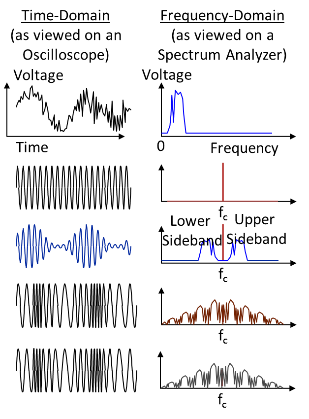
Figure 3. Bandwidth occupancy in AM, FM, and PM signals.
Modulation by Digital Signal [1]
For digital signals, there are several modulation techniques available. The three main digital modulation techniques are:
- Amplitude Shift Keying (ASK)
- Frequency Shift Keying (FSK)
- Phase Shift Keying (PSK)
Figure 4 illustrates the modulated waveforms for an input modulating digital signal. Brief descriptions of each of these digital modulation techniques along with the respective spectral responses and bandwidth are presented below:
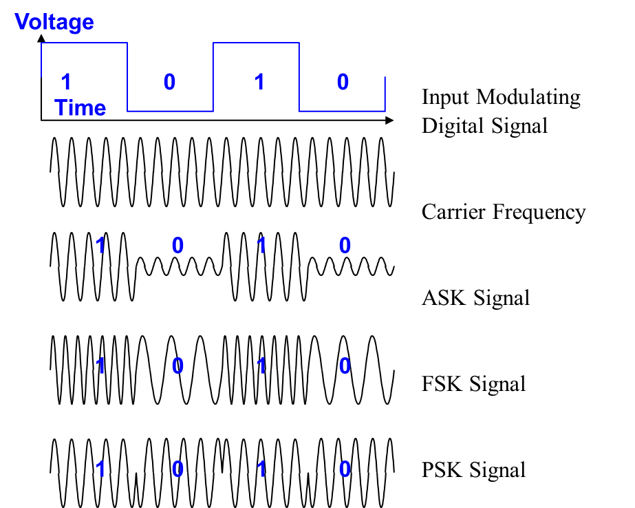
Figure 4. Modulation by digital signal: ASK, FSK, and PSK.
Amplitude Shift Keying (ASK) Modulation
Amplitude shift keying (ASK), also known as On-Off-Keying (OOK), is a method of digital modulation that utilizes amplitude shifting of the relative amplitude of the career frequency [1,8,10]. The signal to be modulated and transmitted is binary; this is referred to as ASK, where the amplitude of the carrier changes in discrete levels, in accordance to the input signal, as shown below:
- Binary 0 (Bit 0): Amplitude = Low
- Binary 1 (Bit 1): Amplitude = High
Figure 4 shows the ASK modulated waveform, where
- Input digital signal is the information we want to transmit.
- Carrier is the radio frequency without modulation.
- Output is the ASK modulated carrier, which has two amplitudes corresponding to the binary input signal. For binary signal 1, the carrier is ON. For the binary signal 0, the carrier is OFF. However, a small residual signal may remain due to noise, interference, etc.
Frequency Shift Keying (FSK) Modulation
Frequency shift keying (FSK) is a method of digital modulation that utilizes frequency shifting of the relative frequency content of the signal [1, 8, 10]. The signal to be modulated and transmitted is binary; this is referred to as binary FSK (BFSK), where the carrier frequency changes in discrete levels, in accordance with the input signal given below:
- Binary 0 (Bit 0): Frequency = f + Δf
- Binary 1 (Bit 1): Frequency = f – Δf
Figure 4 shows the FSK modulated waveform, where
- Input digital signal is the information we want to transmit.
- Carrier is the radio frequency without modulation.
- Output is the FSK modulated carrier, which has two frequencies ω1and ω2, corresponding to the binary input signal.
- These frequencies correspond to the messages binary 0 and 1, respectively.
Phase Shift Keying (PSK) Modulation
Phase Shift keying (PSK) is a method of digital modulation that utilizes phase of the carrier to represent digital signal [1, 8, 10]. The signal to be modulated and transmitted is binary; this is referred to as binary PSK (BPSK), where the phase of the carrier changes in discrete levels, in accordance with the input signal as shown below:
- Binary 0 (Bit 0): Phase1= 0 deg.
- Binary 1 (Bit 1): Phase2= 180 deg.
Figure 4 shows the modulated waveform, where
- Input digital signal is the information we want to transmit.
- Carrier is the radio frequency without modulation.
- Output is the BPSK modulated carrier, which has two phases φ1and φ2 corresponding to the two information bits.
Bandwidth Occupancy in Digital Modulation
ASK Bandwidth at a Glance
In ASK the amplitude of the carrier frequency changes in discrete levels, in accordance with the input signal. Since the input is a digital signal and it contains an infinite number of harmonically related sinusoidal waveforms (according to Fourier transform), and that we keep the fundamental and filter out the higher order components, the bandwidth will be determined by the spectral response of the input modulating signal, centered around the carrier frequency. This is shown in Figure 5. Notice that the spectral response after ASK modulation is the shifted version of the NRZ data. Bandwidth is given by:
BW= 2Rb Hz
where Rb is the input bit rate.
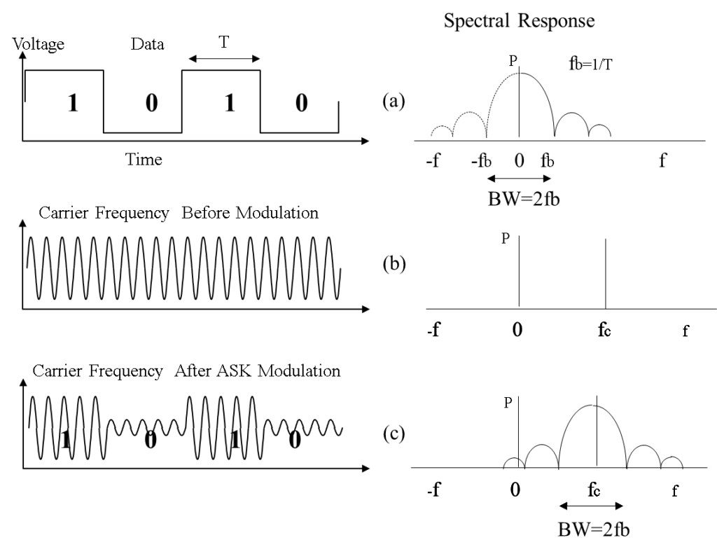
Figure 5. ASK bandwidth at a glance. (a) Spectral response of NRZ data before modulation. (b) Spectral response of the carrier before modulation. (c) Spectral response of the carrier after modulation. The transmission bandwidth is 2fb, where fb is the bit rate and T=1/fb is the bit duration for NRZ data.
FSK Bandwidth at a Glance
In FSK, the frequency of the carrier changes in two discrete levels, in accordance to the input signals. This is depicted in Figure 6. Notice that the carrier frequency after FSK modulation varies back and forth from the nominal frequency fc by + Δfc, where Δfc is the frequency deviation. The FSK bandwidth is given by,
BW=2fb(1+Δfc/fb) = 2fb(1+β) Hz, Where β = Δf/fb is known as the modulation index and fb is the coded bit frequency (bit rate Rb).
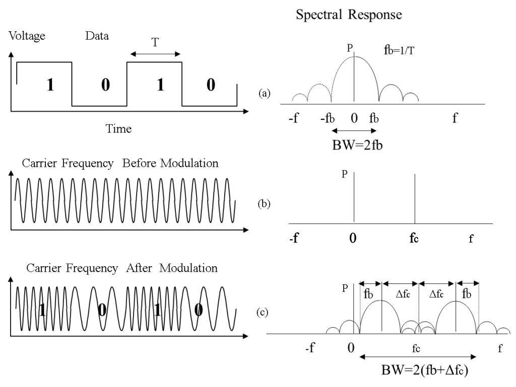
Figure 6. FSK bandwidth at a glance. (a) Spectral response of NRZ data before modulation. (b) Spectral response of the carrier before modulation. (c) Spectral response of the carrier after modulation. The transmission bandwidth is 2(fb+Δfc). fb is the bit rate and Δfc is the frequency deviation=1/fb is the bit duration for NRZ data.
BPSK Bandwidth at a Glance
In BPSK, the phase of the carrier changes in two discrete levels, in accordance to the input signal. Figure 7 shows the spectral response of the BPSK modulator. Since there are two phases, the carrier frequency changes in two discrete levels, one bit per phase, as shown in the figure. Notice that the spectral response after BPSK modulation is the shifted version of the NRZ data, centered on the carrier frequency fc. The transmission bandwidth is given by,
BW(BPSK) = 2Rb/Bit per Phase=2Rb/1=2Rb Hz
where,
- Rb is the bit rate (bit frequency).
- For BPSK, φ =2, one bit per phase.
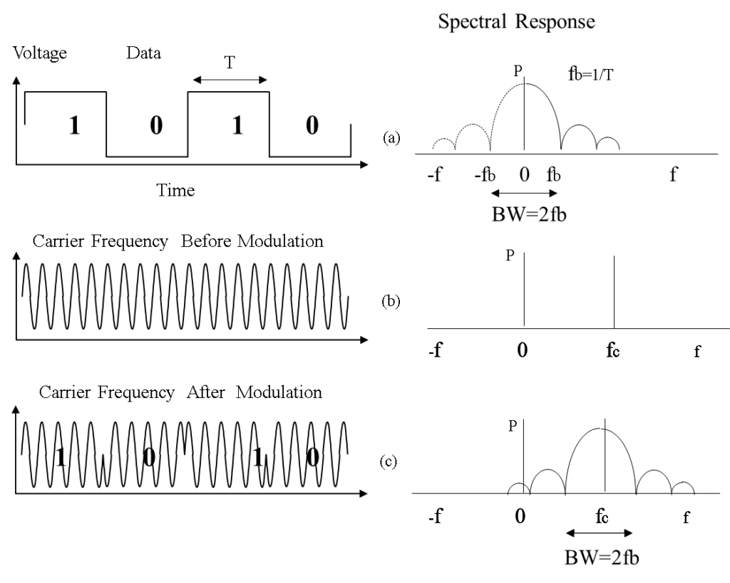
Figure 7. PSK bandwidth at a glance. (a) Spectral response of NRZ data before modulation. (b) Spectral response of the carrier before modulation. (c) Spectral response of the carrier after modulation.
Also, notice that the BPSK bandwidth is the same as the one in ASK modulation. This is due to the fact that the phase of the carrier changes in two discrete levels, while the frequency remains the same.
Conclusions
This article provides a brief overview of modulation techniques described in Radio Frequency Modulation Made Easy (Springer Briefs in Electrical and Computer Engineering) [1]. Numerous illustrations are used to bring readers up-to-date in key concepts, underlying principles and practical applications of various analog and digital modulation techniques. In particular, the following topics are briefly presented in this article:
- Amplitude Modulation (AM)
- Frequency Modulation (FM)
- Amplitude Shift Keying (ASK)
- Frequency Shift Keying (FSK)
- Phase Shift Keying (PSK)
- Bandwidth Occupancy in each of these modulation techniques.
References
- Saleh Faruque, “Radio Frequency Modulation Made Easy”, Springer Briefs in Electrical and Computer Engineering, 2016, 1st Ed. ISBN-13: 978-3319412009, ISBN-10: 3319412000
- Radio Frequency Propagation Made Easy (Springer Briefs in Electrical and Computer Engineering) 1st Ed. ISBN-13: 978-3319113937, ISBN-10: 3319113933
- Saleh Faruque, “Radio Frequency Source Coding Made Easy”, Springer Briefs in Electrical and Computer Engineering, 2015, 1st Ed. ISBN-13: 978-3319156088, ISBN-10: 331915608X
- Saleh Faruque, “Radio Frequency Channel Coding Made Easy”, Springer Briefs in Electrical and Computer Engineering)1st Ed. 2016 Edition. ISBN-13: 978-3319211695, ISBN-10: 3319211692
- Guglielmo Marconi, British patent No. 12,039 (1897) “Improvements in Transmitting Electrical impulses and Signals, and in Apparatus therefor”. Date of Application 2 June 1896; Complete Specification Left, 2 March 1897; Accepted, 2 July 1897 (later claimed by Oliver Lodge to contain his own ideas which he failed to patent).
- Guglielmo Marconi, British patent No. 7,777 (1900) “Improvements in Apparatus for Wireless Telegraphy”. Date of Application 26 April 1900; Complete Specification Left, 25 February 1901; Accepted, 13 April 1901.
- Armstrong, E. H. (May 1936). “A Method of Reducing Disturbances in Radio Signaling by a System of Frequency Modulation”. Proceedings of the IRE (IRE) 24 (5): 689–740. doi:1109/JRPROC.1936.227383.
- David R. Smith, “Digital Transmission Systems”, Van Nostrand Reinhold Co. ISBN: 0442009178, 1985.
- Leon W. Couch II , “Digital and Analog Communication Systems”, 7th Prentice-Hall, Inc., Englewood Cliffs, NJ, 2001. ISBN: 0-13-142492-0
- Bernard Sklar, “Digital Communications Fundamentals and Applications”, Prentice Hall, 1988.
- Fourier, J. B. Joseph; Freeman, Alexander, translator (1878), The Analytical Theory of Heat, The University Press
Author’s note: This article is a brief overview of various modulation techniques covered in the book, Radio Frequency Modulation Made Easy. If my readers are benefited by this contribution, I shall be amply rewarded.
About the Author
 Saleh Faruque is Professor, Department of Electrical Engineering, at University of North Dakota. This article draws from his book, Radio Frequency Modulation Made Easy (Springer Briefs in Electrical and Computer engineering), 2016, 1st Ed. ISBN-13: 978-3319412009, ISBN-10: 3319412000, is the title of the fourth volume in a series comprising six books in Wireless Communications. These books are derived from Dr. Faruque’s class lectures in Communications Engineering, (EE411) and Wireless communications(EE512), and are intended as supplements to recommended texts for engineering students and professionals in wireless communications. The book includes numerous illustrations to bring readers up-to-date in key concepts, underlying principles and practical applications of various analog and digital modulation techniques.
