A Serbian immigrant to the United States, Nikola Tesla is generally recognized as one of the most prolific inventors of all time, having introduced the concept of alternating current (AC), and subsequently designing the first hydroelectric AC power plant installation at Niagara Falls. Beginning in 1893, Tesla also produced and operated numerous radio-controlled contrivances in his New York laboratory. In 1897, he constructed a radio-controlled “telautomaton” in the form of a model boat (Figure 1), which was privately demonstrated for investors at the first Electrical Exposition at Madison Square Garden in September of 1898.
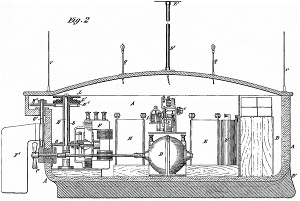
Figure 1. Tesla’s radio-controlled boat, approximately 4 feet long by 3 feet high, employed a series of storage batteries E to power propulsion motor D (bottom center) and steering motor F (adapted from US Patent No. 613,809).
Tesla applied for a patent on his “Method of and Apparatus for Controlling Mechanisms of Moving Vessels or Vehicles” on 1 July 1898, and was awarded US Patent No. 613,809 on 8 November, 1898, the significance of which is twofold. As of this writing, it is the first known reduction to practice of an unmanned radio-controlled system. Secondly, Tesla’s prototype was considerably more advanced in both theory and execution than other 19th-century designs that soon followed. Remote control of multiple subsystems was accommodated, for example, as opposed to the simplistic on-off execution of but a single function.
Perhaps the most noteworthy implication of Tesla’s radio-controlled automaton, however, was demonstration of the basic “AND-gate” function that would become an indispensable element of all subsequent electronic and computer logic. His inspiration for this concept reportedly came from studying the work of Victorian biologist and philosopher Herbert Spencer regarding the combined action of two or more nerves in the human body. Tesla’s original implementation employed two sets of transmitters and receivers operating on different radio frequencies to trigger a pair of detector relays. Both these relays had to close at the same time in order to energize a third, which in turn incremented a mechanical escapement driving a rotary switch to decode the command.
The motivation behind this dual-channel approach, which Tesla dubbed “the art of individualization,” was to minimize the chances of false activation of the control circuitry due to outside interference. This logical-AND feature was not described in Tesla’s patent application dated 1 July 1898, however, for reasons he later explained in My Inventions (1919):
“It is unfortunate that in this patent, following the advice of my attorneys, I indicated the control as being effected through the medium of a single circuit and a well-known form of detector, for the reason that I had not yet secured protection on my methods and apparatus for individualization.”
Following successful resolution of a potential interference with a patent submitted by Reginald Fessenden, Tesla was finally awarded US Patent No. 725,605 on 14 April 1903. The AND-logic employed by the receiver circuitry depicted in this document is shown in Figure 2.
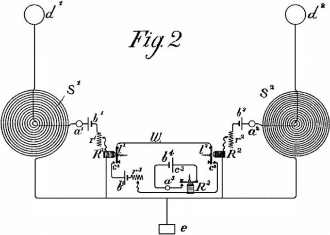
Figure 2. Tesla’s dual-receiver design provided a relay-based AND-gate function that allowed the contacts of R3 to close only when both R1 and R2 were activated by their respective signals (digitally enhanced from US Patent No. 725,605, awarded 14 April 1903).
A similar logical-AND implementation, however, had been previously disclosed in a patent application submitted by English inventors Ernest Wilson and Charles John Evans on 28 July 1898. US Patent No. 663,400 was subsequently awarded them on 4 December 1900. In his 1916 book, Radiodynamics, Benjamin Miessner indicates that Ernest Wilson was granted an English patent in 1897 for “wireless control of dirigible self-propelled vessels”:
“The primary object of this invention was to provide a weapon for use in naval warfare, which, if in the form of a dirigible torpedo, controlled from a shore or ship wireless installation, would be most deadly in its effect on a hostile fleet.”
Miessner claimed at the time that Wilson never reduced his idea to practice.
On the other hand, in Chapter XXIX of History of Communications-Electronics in the United States Navy (1963), Captain (Ret.) Linwood S. Howeth reports:
“In 1887, Englishmen E. Wilson and C. J. Evans were successful in controlling slow-moving boats by radio on the Thames River. In 1900 they were granted U.S. Patent No. 663,400 on their method.”
The cited date “1887” above was probably a typographical error that should have read “1897,” as their receiver design employed a coherer-type detector, which had not been introduced by Edouard Branly until 1890. Furthermore, the US patent application was submitted on 28 July, 1898, for which the pair received US Patent 663,400 on 4 December 1900.
Born in 1863, Ernest Wilson was an assistant professor in the Electrical Engineering Department at King’s College, London, from 1897 to 1898, at which time he was promoted to full professor. On 26 March, 1898, he and Evans were awarded British Patent No. 7,382 entitled “Improvements in Methods of Steering Torpedoes and Submarine Boats.” Their radio-control scheme addressed steering only, employing two separate transmitters and receivers for deflecting the rudder both left and right. Two orthogonal antennae dipoles were used to achieve signal discrimination as shown in Figure 3.
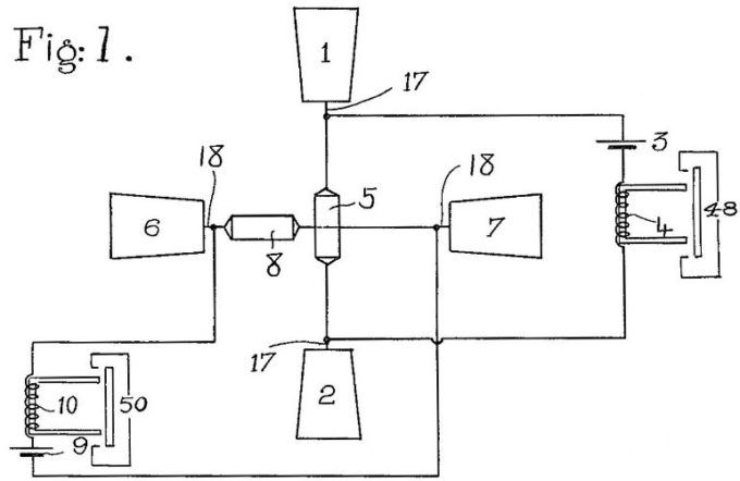
Figure 3. Two separate broadband receivers were employed, their antennae pairs 1-2 and 6-7 arranged orthogonally (i.e., one vertical and one horizontal) for two-channel selectivity (adapted from US Patent No. 663,400, 1900).
The accompanying dual-transmitter configuration is schematically presented in Figure 4. The high voltages generated by Ruhmkorff induction coils 15 and 23 were presented across spark gaps associated with antenna pairs 11–12 and 21–22, which were orthogonally aligned with respect to one another. The underlying theory of this arrangement was that the vertically oriented dipole 11–12 would have maximum coupling with the vertical receiving antenna 1–2 shown earlier in Figure 3, and minimal coupling with the horizontally aligned antenna 6–7. Conversely, the horizontally oriented transmitting antenna 21–22 would couple with receiving dipole 6–7 and not 1–2.
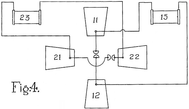
Figure 4. The two separate spark-gap transmitter configurations had their dipole antenna pairs 11-12 and 21-22 arranged orthogonally in similar fashion to the receiver (adapted from US Patent No. 663,400, 1900).
The relay logic of Figure 5 was used to decode this either-or-both scenario to allow a third command state, the first two of course being turn left and turn right. The untuned receiver depicted on the left side of the diagram contains the standard components of battery 3, coherer 5, and relay 4 (which opens and closes circuit 48). An identical receiver configuration is shown on the right. Situated between them, however, is a third relay with two separate field coils 19 and 20, individually wired in series with receiver relays 4 and 10, respectively. The sensitivity of this third relay was adjusted such that it would pull in only when both of its field coils were energized, which only happened when the two receivers simultaneously detected a control signal.
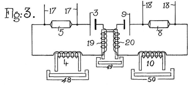
Figure 5. The AND-gate configuration of Wilson and Evans shows how circuit 49 was activated whenever relays 4 and 10 were both energized (adapted from US Patent No. 663,400, 1900).
This AND-gate function, which served to close circuit 49 when both receivers detected a radio signal, was fully described and illustrated in US Patent No. 663,400, filed 28 July 1898, which also included the alternative embodiment of Figure 6. As previously discussed, Nikola Tesla did not submit his comparable “art of individualization” patent application until some two years later on 18 July 1900, but afterwards claimed to have incorporated it on his first radio-controlled prototype boat. Surviving photographs of this vessel, however, reveal only a single antenna of the type depicted in the patent drawing reproduced earlier as Figure 1.
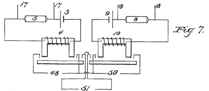
Figure 6. An alternative logical-AND configuration using double-pole-single-throw detection relays to activate circuit 51 whenever relays 4 and 10 were both energized (adapted from US Patent No. 7,382, 1900).
About the Author
 Commander (Ret.) H.R. (Bart) Everett is the former Technical Director for Robotics at the Space and Naval Warfare Systems Center Pacific in San Diego, CA. In this capacity he has served as Technical Director for the Idaho National Laboratory (INL) Advanced Unmanned Systems Development Program funded by the Office of the Secretary of Defense (OSD), Technical Director for the Army’s Mobile Detection Assessment Response System (MDARS) robotic security program, and chief engineer for the USMC Ground Air Robotic System (GATORS). He is the former Director of the Office of Robotics and Autonomous Systems (SEA-90G), Naval Sea Systems Command, Washington, DC, and has been active in the field of robotics for over 50 years, with personal involvement in the development of over 40 mobile robotic systems, with an emphasis on sensors and autonomy. He has published more than 125 technical papers and reports (including several books), and has 21 related patents issued or pending. He serves on the Editorial Board for Robotics and Autonomous Systems magazine and is a member of IEEE and Sigma Xi. This article draws from his book, Unmanned Systems of World Wars I and II, MIT Press, 2015. Find him on Twitter: @HRBartEverett
