
This article aims to describe in simple terms how a fluxgate operates, its use as a component in a gradiometer or on its own simply to measure the Earth’s or other similarly low magnetic field. There is no such thing as a definitive fluxgate design, there being many variants, each using differing approaches and materials. However, they all operate on the same basic principle. Design ideas will be presented to enable an experienced person, with the use of basic electronics equipment, to experiment with magnetic components, use these in a working fluxgate, and ultimately construct a gradiometer. Much tuning of the design may be required, but is likely to lead to a very satisfactory outcome.
Fluxgate Background
The fluxgate magnetometer is a magnetic field sensor for vector magnetic field, measuring its intensity and direction. Its normal range is suitable for measuring Earth’s field and it is capable of resolving well below one 10,000th of that. It has traditionally been used for navigation and compass work, as well as metal detection and prospecting in the form of a gradiometer.
Designs fall into broadly two styles, those employing twin rod cores and those using ring cores. The rod cores were the first to be developed from about 1930 onwards, and the ring core models, although appearing at about the same time, were not really developed until 1962, when they were rapidly accepted as a serious contender to the rod core. While there are many alternative designs, none have reached the state of development and performance attributed to those mentioned here, which, in addition, easily outperform micro devices such as those in phones and other handheld devices.
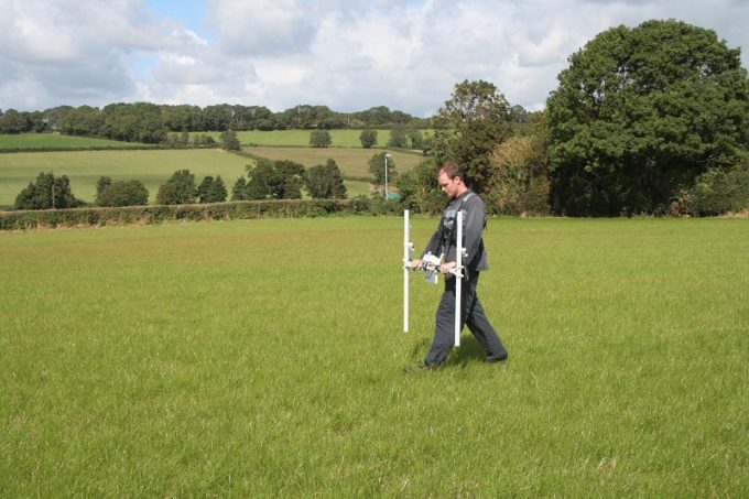
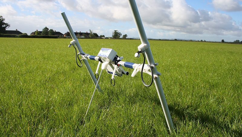
A fluxgate gradiometer in field use. Photo courtesy of Thames Valley Archaeological Services / www.tvas.co.uk
General Mode of Operation
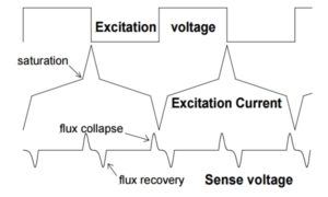
Figure 1. Ideal fluxgate waveforms
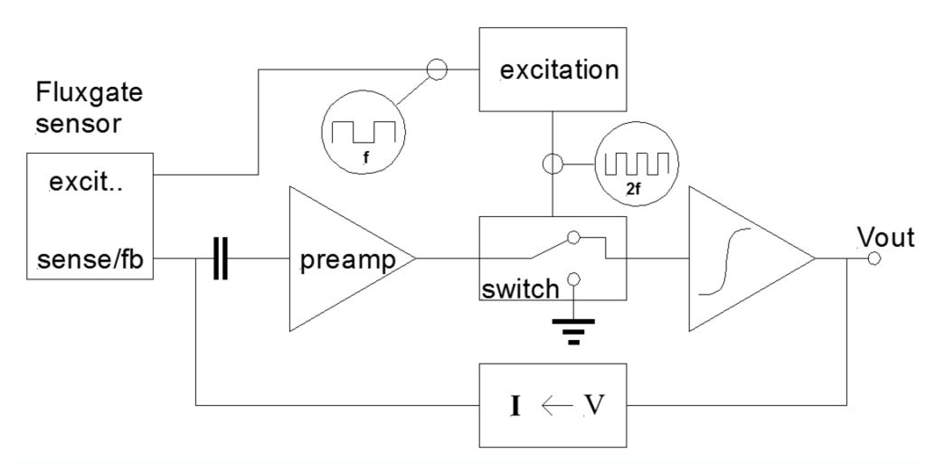
All fluxgates use a highly permeable core which serves to concentrate the magnetic field to be measured within itself. The core is magnetically saturated alternatively in opposing directions along any suitable axis, normally by means of an excitation coil driven by a sine or square waveform. Prior to saturation any local ambient field is channeled through the core producing a high flux due to its high permeability. At the point of saturation, the core permeability falls away to that of vacuum, causing the local flux to collapse. During the next half cycle of the excitation waveform, the core recovers from saturation, and the flux, due to the ambient field, is once again at a high level until the core saturates in the opposite direction; the cycle then repeats. Despite the magnetization reversals due to the excitation, the flux from the ambient field operates in the same direction throughout. A sense coil placed around the core will pick up these flux changes, the sign of the induced voltage indicating flux collapse or recovery.
The name “fluxgate” clearly derives from the action of the core gating flux in and out of the sense coil. This process is shown in figure 1 as idealized waveforms, and it can clearly be seen that the sense voltage is twice the frequency of the excitation. Demodulation schemes often employ 2nd harmonic detection for this reason. In practice, for a single rod-shaped core, the sense coil will pick up the excitation drive as well as the signal voltage, which, due to its high level, can prove troublesome to remove electronically. A common solution for this is to use two parallel cores with the excitation phase reversed from one to the other. The sense coil picks up the signal but the induced excitation voltage is cancelled by the phase reversal, producing waveforms similar to those in figure 1.
As described, the voltage of the flux change peaks is from Faraday’s law proportional to the magnetic field; a simple sensor can be used in this way. However a superior design will employ a coil (the sense coil can double-up for this task) to feed back a magnetic field in opposition to the sensed field such that the two fields cancel one another. In this mode of operation, where the fluxgate is used as a null detector, the current in the feedback coil is proportional to the sensed field. The technique improves linearity of measurement, and allows a much greater dynamic range to be achieved.
Rod Core Design
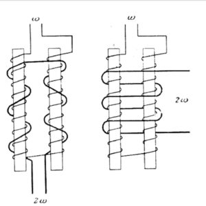
Figure 2. Rod Core Fluxgates.
The two common types of twin rod core design are shown in figure 2, with the Förster-based version on the left and the Vacquier on the right. These designs closely follow the design principles discussed above, with differences only in the sense coil configuration. The separate sense coils on the Förster design are phased such that they cancel the excitation while combining the signal voltages. It is possible to build a fluxgate based on the Förster using a common set of coils for excitation and sensing.
Core material for the rod was traditionally high-permeability mu-metal wire. The rod is typically 20mm in length, but can vary from 15 – 75mm.
These designs are good for directional sensitivity with the anisotropy of the core defining the sense direction. They are universally favored by the geomagnetic community for their long term stability. This can be better than 3nT per year.
Ring Core Design
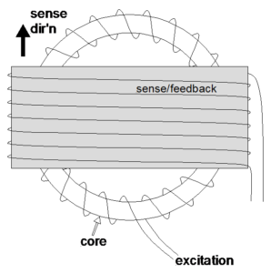
Figure 3. Ring core fluxgate.
The ring core is really a logical extension of the twin rod core where the rods are connected top and bottom and a continuous magnetic circuit is formed. These normally use a toroidal excitation winding spread evenly around the ring core, with a sense winding around the outside and orthogonal to the plane of the core, equivalent to the Vaquier rod core design. The axis of the sense/feedback winding defines the sensitive direction of the sensor, since the core is isotropic. It is feasible to put two sets of sense coils over the toroid at right angles to one another and create a two-axis (XY) sensor.
Gradiometers
Field gradient measurement fluxgates or gradiometers can be designed to measure axial or transverse magnetic field gradients. This distinction is important, because geophysical measurements often measure a single magnetic axis of the Earth’s field. However, while near the equator, the horizontal component is totally dominant, as the location moves toward either pole, vertical will increasingly take over. The instruments are usually based on two conventional fluxgates separated by a certain distance, the baseline, on a rigid boom or tube. Baselines of 0.5m to 1m are typical on a vertical field component gradiometer. The difference in output between the fluxgates over the baseline is a measure of the field gradient.
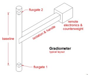
Figure 4. Typical fluxgate gradiometer layout.
Any type of fluxgate can be used, but if a twin axis ring core is used, both axial and transverse gradients can be measured by selecting the desired outputs and differencing them. A rod core device based on the Förster design has the advantage that the two core halves and their respective coil assemblies can be physically separated while remaining operational. If the excitation and sense coil phases are reversed to one core, the device will now measure the magnetic field difference between the cores. In this mode the feedback current does not null the “average” field but rather equalizes the fields seen at each core. All that remains is to place the core assemblies along an appropriate baseline and the device becomes a true gradiometer, which can be configured to measure axially or transversely. It is important to precisely align the axes of the two baseline sensors to avoid measurement errors. The electronic operation of these sensors is generally the same as normal fluxgates. This class of fluxgate gradiometer will not react to normal Earth’s field in a clean magnetic environment, but only gradients in the field. This is precisely the use case seen in the field application described here.
Performance
Stability and noise performance of rod core and ring core devices using state of the art core materials is very comparable. However, the sense direction of the rod core is better defined and controlled by the anisotropy of the core. The ring device directivity is defined by the outer sense winding, and is possibly less predictable because of this. Additionally the ready availability of suitable high-performance ring cores is poor. These factors tend to tip the balance towards a rod core preference for use in a gradiometer, which will be the subject of the remaining part of this article.
Core Materials
The prerequisite for a fluxgate magnetometer core is high permeability and low coercivity, which has been well-satisfied by mu-metal traditionally, which can be used for a rod or ring core device. Much of the research effort since the 1960s has been in understanding the contribution of the core to the fluxgate performance. This is now reasonably well understood. The smallest core mass should be used, and to achieve the lowest noise a material with low magnetostriction, low saturation induction (Bmax) and low Curie temperature should be chosen. The available materials fall into two camps: conventional crystalline alloys and the amorphous or glassy metals.
Of the former, the most likely to be found is mu-metal, preferably in a wire form, although thin strips of foil could work. Carpenter metals, the manufacturer, also produce much more exotic, and expensive, nickel-iron materials of a similar nature, e.g., various permalloys.

Figure 5. Tyco Sensormatic EAS device.
The second option is actually much more exotic, but by happy chance there is now a common use for this material. EAS (electronic article surveillance) labels are often used on medium-priced retail goods such as DVD or Blu-Ray cases to sound an alarm at the store exit portal if not de-activated at the till. The one illustrated here, by Tyco, and branded Sensormatic, has a barcode, which is actually fake. Other brands can be plain. These tags are usually self-adhesive, but if carefully peeled off without too much bending, they can be opened by slitting down one side with a sharp blade.
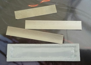
Figure 6. EAS strip deconstructed.
Inside, as shown here, are three metal strips, two long and one short. The long ones are made from amorphous metal, and have definite potential for fluxgate use. The shorter, thicker one is a weak magnet, used to activate the device. The amorphous strips are cut to a precise length of 37mm, which allows them to resonate at 58kHz when in the magnet’s field. The interrogation equipment located by the doorway can detect this resonance. If removed carefully without scratching or bending, the amorphous strips can be repurposed as fluxgate cores. Although a ready supply of these tags might be available from purchased items, small quantities of new ones may also be found from the usual online sources. Used or not, they will all be suitable.
It should be noted that although strongly attracted to magnets, the long strips cannot be themselves permanently magnetized to behave as a magnet, whereas the short one can. This is testimony to the soft magnetic nature of the amorphous material, essential for fluxgate use.
Fluxgate Design/Construction
Core Magnetics
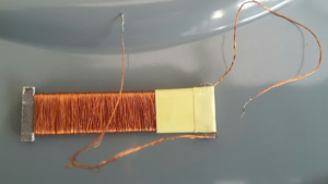 One of the first tasks in using a new core material is to check out its magnetic performance. To this end it is useful to build a close fitting wire coil to magnetically energize the core. A suitable coil of about 1,000 turns using 0.1 to 0.2mm enameled copper wire can easily be made on a flat cardboard former or bobbin. A three-layer sandwich form, glued together, to form a long central cavity to accommodate the strip core, is suggested. The picture here shows just such a coil made from a business card. It has a flattened H shape, the bar dimension being 45x10mm to take the winding. The central hole/slot, open at the left side only, is 6.5mm wide and 41mm deep from the left winding end. This is to locate the core centrally with overlap at the ends to ensure complete magnetization. The end ‘cheeks’ are not critical but are 3mm wide by 14mm overall height as shown. This winding is scramble-wound by hand, covering about three layers; it should be evenly distributed along the length. The Sensormatic cores, at 6×0.03mm section, easily slip inside the coil.
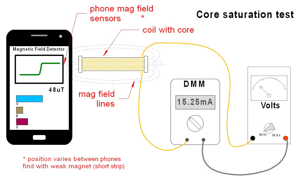
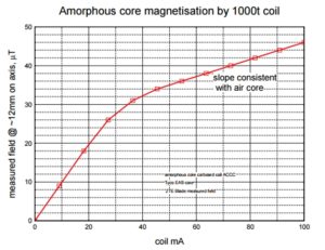
A quick rough and ready test is to power the coil with core fitted from a variable DC power supply, at the same time measuring the magnetic field created at the end. An old Android phone was used with a “Magnetic Field Detector” App to produce this curve. The core saturation point is clearly shown as a slope change at about 30mA. The voltage used for this test was limited to about 5V to avoid overheating this 55 Ohm coil. The resistance could be beneficially reduced with thicker wire than the 0.1mm used.
Frequency Tuning
For the electronics development it is essential to test the coil/core assembly further, using a square wave drive over the range 1kHz to 20kHz, and an oscilloscope, using perhaps a 4R7 resistor to measure the current waveform. This can be adjusted to look like the Excitation Current of figure 1 above, by varying the frequency and voltage drive, V. To reach core saturation, the frequency must be low enough to allow the coil current to reach core saturation well inside each half cycle. The current slope, in A/s, is given by the voltage to inductance ratio, V/L, and is independent of frequency. This is an approximation, disregarding coil resistance which holds up to currents of about V/3R.
 The coil example above had an inductance of about 4mH, measured. So at 5V drive the current slope is 5/0.004, 1250Amps/second. Meaning it will take about 0.03/1250, 24µs to saturate. Allowing one third of the square wave period, the entire period would be 74µs, giving an acceptable operating frequency of some 13kHz.
These calculations hopefully show the relationship between coil/core inductance, frequency, and drive voltage. All these parameters, including coil turns, can be adjusted to optimize the design. This is much easier to visualize on the oscilloscope, with a benchtop oscillator/function generator to drive the coil. Once again, there is an excellent function generator app on the Google Play Store from Kewlsoft which should work well here, preferably with a buffer amplifier to give some relief to the phone/tablet.
Core Optimization
At this juncture it should be apparent that the core characteristics have had a large bearing on the “design” so far. It should also be noted that a twin core device needs to have well-matched cores and coils, for good elimination of odd harmonics. A gradiometer will need two fluxgates, so possibly as many as four cores. The EAS strips are likely to be reasonably well-matched, at least in one tag, and hopefully from one tag to another of the same manufacturer, but not perhaps between manufacturers. The coil can be used to measure individual strips with some imagination. The width of the strips is quite large for fluxgate use, with a high mass, potentially affecting noise and resolution. Only testing will reveal performance. Suffice it to say that smaller cores would probably improve things, and could be addressed by cutting the strips into thinner pieces, which is possible with a sharp pair of scissors. However, it might now be difficult to maintain good matching. Also note that only low temperature mechanical working of these materials is advisable. Of course different sizes will require a revised coil design, which should fit as closely to the core as possible, and appropriate electronics adjustments.
The use of mu-metal and similar alloys has been somewhat ignored thus far, but a quick comment is in order. To prepare, for example, wire cores of perhaps 0.4mm diameter, best performance requires heat treatment, typically 1100°C in a hydrogen atmosphere with a slow cool. After this, mechanical damage such as bending or cutting will degrade them, so they need to be protected until installed into the fluxgate. It is possible to achieve some limited success by heating these cores in a naked flame, but that will require considerable experimentation. Amorphous material is much more tolerable of mechanical damage, so it can be bent and cut without too much concern. It, too, however, can benefit from annealing, but at a much more reasonable 250°C, and better still with an axial magnetic field applied. The condition of the strips discussed above is unknown, but may well already be in this state for its EAS application.
Fluxgate Coil Windings
For use in a fluxgate the cardboard coil former may work for a quick prototype, but is not a good long-term prospect for repeatable performance, which requires well defined, matched and stable coil forms. One possible approach is to employ a similar design to the cardboard, but using thin Alumina or Macor sheet, possibly even thin plastic. While the latter is the least preferred choice, this general approach could be used to produce a twin core fluxgate by bonding two coil assemblies together. Application of varnish to the coils can also help improve stability, but is difficult to optimize in terms of flexibility and expansion.
The strip or rod cores, owing to their shape, anisotropy control the sense direction and so they must be precisely located by the formers; a sense/feedback coil restricted to the central region should reduce noise. Winding directly over the paired coil assemblies as in the Vacquier design, figure 2, is possibly the easiest approach. The coefficient of expansion of this coil with temperature is the primary factor controlling the temperature coefficient of the fluxgate, as it expands, moving the turns apart creating a negative temperature coefficient. This is probably of less concern for a gradiometer than a fluxgate used alone, because the differencing should reduce the effect. The coil will again need to be many hundreds of turns, subject to optimization. The use of a transformer drive from the electronics could eliminate the need for this extra coil, for the inconvenience of this extra custom component.
Once built and connected to the electronics, failure to operate properly can often be traced to reversed or otherwise wrongly connected coil connections. A phase reversal, the equivalent of turning the core/coil through 180° with the wiring unaltered, can sometimes result in a differential fluxgate, as referred to in the gradiometer section previously.
On a more practical note it is all too easy to incorporate materials into the fluxgate design which have small and not very obvious magnetic moments, which can then introduce mysterious offsets. A prime candidate for this must be connection pins, where plating often conceals a magnetic nickel layer; test items with a Neodymium Iron Boron magnet.
General Electronics Requirements
Good results for excitation of the core can be obtained with a square wave, and this is certainly easier to generate than a sine, so is to be recommended. Digital generation of square wave excitation, together with a 2f reference frequency, is conveniently accomplished by means of a microcontroller or a few discrete logic devices. To ensure good low noise, the core material should be driven well into saturation by 10 to 100 times its saturation field. Transformer drive with a grounded center tap secondary, can eliminate the need for a sense/fb coil and is often employed. Easier capacitive drive can also be used with a feedback coil, provided that low leakage capacitors are chosen to avoid spurious and variable offsets. To reiterate, the voltage drive to the fluxgate together with the excitation coil inductance, determine the current ramp rate in the coil, and therefore the maximum frequency attainable. If the frequency is too high for the cores to reach saturation, the device will simply not work at all. If too low it will result in excessive power consumption and possible overheating. The drive voltage should therefore be chosen to suit the frequency desired, with attention paid to the saturation point of the core within the cycle. (Generally, for this class of electronics, working below about 20kHz or even 10kHz is preferable, as it results in easier circuit design, as well as the use of “entry” grade test equipment like oscilloscopes, function generators, etc. One benefit to operation at higher frequencies is the ability to follow rapid field changes, however this is not usually required for these field levels, especially for geomagnetic work of this nature.) In this context one advantage of using a microcontroller to generate the waveforms is the ability to easily adjust the phase shift between the f and 2f outputs for better control of the demodulation.
The sense winding is normally fed into a preamp with mild tuning at the 2nd harmonic of excitation frequency. In practice this can cause problems because of pulse stretching of the voltage spikes passing through, and a broader band amplifier with a reasonably high slew rate can help avoid this.
Demodulation is usually accomplished with a phase-sensitive detector, typically a CMOS analogue switch, following the preamp. It is important to choose a switch with low charge injection to avoid further offset problems. The switch drives an op-amp integrator, which needs to be a low offset, low temperature coefficient device. The integrator time constant is chosen as a compromise between response time and noise performance.
The feedback voltage to current converter can be as simple as a resistor, or an active device such as a transconductance amplifier can be employed. When a resistor is used, its temperature coefficient will be added directly to the magnetic field measurement, so care needs to be taken here. In addition, should the voltage from the integrator be taken as the field output, the proportion of voltage across the feedback coil will be subject to the large temperature coefficient of copper. This can be taken out in software or by the use of additional analogue circuitry. Where a microprocessor is available, the former solution is preferable, providing a more accurate result and less interference to the low level sense signal from the fluxgate.
Closing Remarks
Having got this far it is essential to point out that geophysical gradiometers are not as simple as metal detectors; they produce very small signals—magnetic pixels—from tiny anomalies like bits of old wood or fire ash, for example. Not the sort of things you would dig up immediately, as a metal detectorist might. So commercial gradiometers have built-in data capture (logging) facilities which, together with a planned survey (moving over a prescribed grid pattern), and importantly, PC software, will produce an image of the area. A bit like an x-ray, slightly indistinct, but often showing large features for interpretation, possibly an old wall, ditch, temple foundation, etc. Then the archaeologists can take over with their brushes and trowels.
This data management aspect is beyond the scope of this article. The device described so far will produce the basic real time signal alone. A person with just a gradiometer sensor may be lucky with a big signal, perhaps from a Greek amphora or similar, but it is not very likely. It would certainly be possible to again use a smartphone or tablet with this basic gradiometer to emulate the commercial offerings. For example, a Bluetooth connection to the phone, which can request magnetic data, manage grid location by step counting and GPS, all logged to memory. It could then offload to a PC or even do some processing itself to produce an image. Any takers?
There are, of course, other non-geophysical uses which can be imagined for these devices, perhaps in a more controlled and predictable environment. The movement, or detection of iron-based objects over moderate distances, dependent on their size, could be accomplished. The detection or counting of vehicles or boats at several tens of meters, or even personal weapons at somewhat closer separation spring to mind.
The building of fluxgates and gradiometers is a surprisingly complex task, but one which pays back attention to experimentation and detail. It is likely that almost any design can be improved by further research into mechanics, electronics, and magnetics, leading to a rewarding understanding of this fascinating technology.
About the Author
Ken Evans is the Founder of Invasens, based in the UK, a provider of short-term and periodic sensor engineering services to companies as an alternative to more permanent staff. Ken specializes in OEM sensor or transducer design, including customization, selection, testing, and proving strategy, providing cost effective, targeted resources without recruiting headaches. A Chartered Engineer and IET member, he obtained degrees in Electronics and Solid State at Liverpool and Manchester Universities. Prior to Invasens he held senior sensor design roles with leading companies in automotive fuel injection and in oilfield downhole navigation technologies. He is familiar with, and has worked on, devices involving the science of electric field, piezo, optics, thermal, chemical, and magnetism in their broadest senses with numerous client companies. Although specializing in analogue electronics, usually the primary sensor interface, Ken has also been involved with direct sensor microprocessor input and control. Especially interested in innovation, he has a number of patents to his name.
