
In the fast-paced world of electronics, new devices are constantly introduced. Hardly a day goes by without some new development that will prove to have a major impact on everyday life. Few, though, have had more of an impact than the humble optoisolator. This device has revolutionized digital electronics with its ability to interface just about anything.
In the Beginning
Early in the development of computers, it quickly became clear that they were going to have a permanent impact on everyday life. As research and development programs expanded the computer’s domain, it was also evident that better interface devices would be necessary. Relays were capable of simple turn-on/turn-off duties, but because the relay is a mechanical device, high-speed digital signals processing was not possible.
Optical Considerations
The development of light-sensitive transistors opened the door to new possibilities, but unfortunately, at that time all light-producing devices were of the incandescent variety. This type of illumination produces light by heating up a filament, which is too slow to come on and too slow to go off in order for it function as a high-speed digital communication method.
The LED
When researchers discovered how to electrically stimulate photons to produce light without heat, the LED made its appearance and provided the final link in the quest for a fast-responding interface. Small 6-pin DIP ICs started cropping up everywhere, and now optoisolators are ubiquitous. Figure 1 shows the two types of standard optoisolators, biased and unbiased. The biased type DIP uses pin 6 to turn the light sensitive transistor on or off, which overrides the signal fed to the LED. This feature is more likely to be found in computer devices where the processing of a multitude of signals are combined.
Applications
Since the principles of optical control eliminate such problems as circuit loading, impedance matching, circuit interaction, and ground loop distortion, the optoisolator appears to be the perfect interface. So perfect, in fact, that the MIDI system (Musical Instrument Digital Interface) uses optoisolators exclusively to communicate from one digital synthesizer to another.
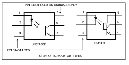
Figure 1. The two types of standard optoisolators, biased and unbiased.
Telephone equipment today is replete with optical devices and the result is clearer phone quality. Television design engineers are also taking advantage of the new optic technology. Indeed, the entire television industry is incorporating the new optics.
Current research is investigating the possibility of simplifying elaborate IC circuitry with the use of internal optical linking techniques. Everywhere research is opening up new possibilities with the use of new optics. As LASERs impacted the advance of computer technology, so too will the use of optical interfacing. So step up and prepare by picking up a few optoisolators and constructing the OP-1 designed below, and see for yourself how you can begin to apply this amazing technology.
Case Types
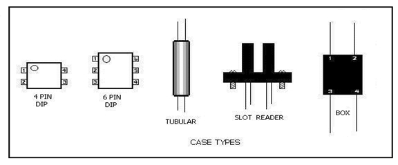
Figure 2. The different types of optoisolators, classified by case type.
Figure 2 shows different types of optoisolators. A 4-pin version of the DIP is available, as well as a tubular, a slot reader, and the box type. As these devices become increasingly popular, a wider variety of sizes and shapes will appear. The current crop of 6-pin units does not make use of pin 3, however, this may change in the future. Since LEDs and LSTs (Light-sensitive Transistors), are available separately, it is possible to build your own optoisolator. If you choose to construct your own, take a look at Figure 3 for details. Aluminum spacers are ideally suited to the fabrication of your own optoisolators.
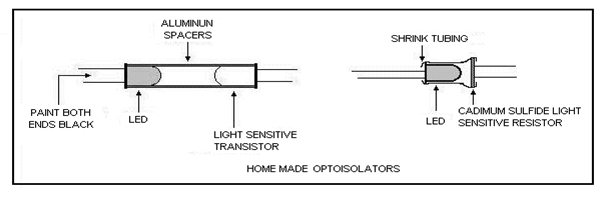
Figure 3. DIY optoisolators.
Make sure that the ends are painted black or use shrink tubing to block the light at the two ends. Any color LED will do, however, green works best. Cadmium sulfide light-sensitive resistors can be substituted for light sensitive transistors if the demands of the circuit are not too critical. Make sure that the LED is mounted very close to the resistor so the shrink tubing does not interfere with the light transfer.
Optoisolator Speed
Inexpensive optoisolators may have a limited frequency that would eliminate them as candidates for some circuit applications. With a few added components though, the response time can be trimmed to make the device compatible with a wider range of designs.
The LED can be enhanced with a reverse biased diode wired in parallel. This acts as a clamp to stabilize and shorten the response time of the LED. As you can see in Figure 4, diode D2 also acts like a clamp, and resistor R2 provides a ground reference to shut down the transistor as soon as the light has diminished to a certain level.
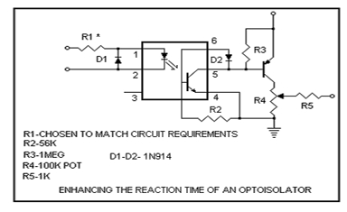
Figure 4. Trimming the optoisolator’s response time.
OP-1 Tester
If you are an electronics enthusiast but have not yet worked with optoisolators or optocouplers, you can be certain that you will eventually, and when you do, you will need a way to test them. That’s where the OP-1 comes in. It can test and evaluate the performance of any optoisolator on the market. The socket accommodates the standard 6-pin DIP case, while the test leads will serve for any other configuration.
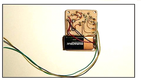
Figure 5. The OP-1 optoisolator tester.
Schematic
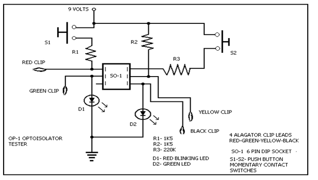
Figure 6. Schematic diagram of the OP-1 optoisolator tester.
Parts List
- A 2 1/8 by 3 3/8-plastic box
- Four alligator clip leads
- Resistor 1 – 1k5
- Resistor 2 – 1k5
- Resistor 3 – 220
- S1 momentary contact push button switch
- S2 momentary contact push button switch
- D1 – Red LED
- D2 – Green LED
- SO-1 six pin optoisollator socket
- Copper clad circuit board.
Principles of Operation
Place an optoisolator in the socket. Press the test button and you should see both LEDs blink in unison. If the green LED is dim or comes on and goes on slower, the device is not suited for high-frequency interfacing, but may be useful in less critical circuits. No flashing at all means that the LED is open. Red flashing without the green means an open transistor.
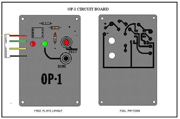
Figure 7. OP-1 circuit board layout.
A biasing test button is provided, and when pressed should light only the green LED as long as you hold it down. In the event that the green LED does not light, it merely means that the device is not equipped with a biasing facility.
To make sure that the device is functioning properly, connect the red and green clips and then press the test button. If the device is functioning properly, the red LED should blink. To test the biasing section, connect the black and yellow leads, and the green LED should stay on for as long as the leads are connected.
Construction
A 2 1/8 by 3 3/8-plastic box was chosen for a cabinet. This type of container comes with a metal top, which was used as a template to cut a foil-covered circuit board to replace the metal cover. In addition to the foil pattern, the board adds strength and stability to the cabinet. All components are flush-mounted to the board and an 8-pin socket with two of the pins sanded down to accommodate the 6-pin variety unit. Test leads can be made from experimenter test leads available at your local supplier.
The circuit is powered by a 9-volt battery, which is connected to the circuit with a battery clip and secured to the board with double-sided tape. It’s a snug fit in the plastic box so the unit will feel stable. The switches are connected to the board with telephone wire. Figure 7 also provides an illustration of the foil pattern with component placement that you can use as a guide for your own circuit.
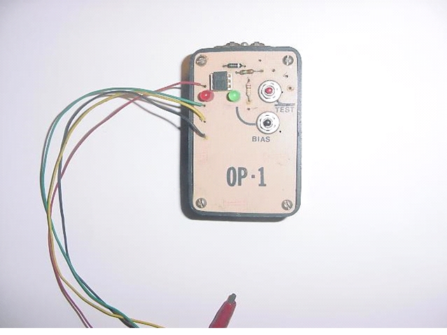
Figure 8. The completed OP-1 optoisolator tester.
Conclusion
With the advent of the new optic technology, it will serve you well to investigate the many possible uses for optoisolators in your designs. They just may simplify your designs, and provide you with the opportunity to join the light generation!
