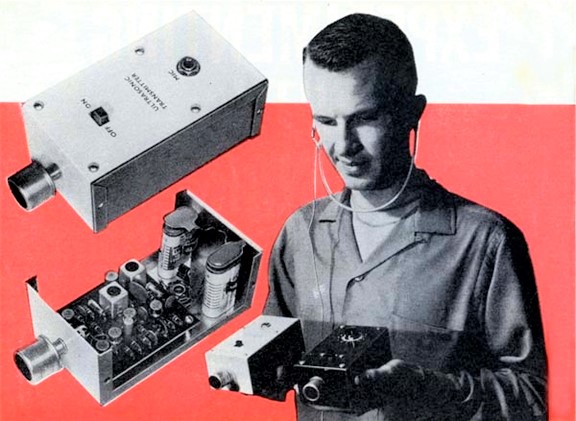
About this March, 1963 feature, Popular Electronics asks, “How would you build this circuit today?” Share your ideas with us. The best idea will be rewarded with a $1,000 shopping spree at Adafruit!
Note that we’ve retained the old conventions used in the original, e.g., kc versus MHz, μμf versus pf, r.f. versus RF, etc.
***
 Here’s an old circuit with a new twist—basically a superheterodyne, it brings the not-so-audible world above 16,000 cycles to human ears.
ARE YOU AWARE that a dog can hear sounds which, if you relied on your ears alone, you probably wouldn’t even know existed? This is because human ears—unlike dogs’ ears—aren’t sensitive to sounds much above 16,000 cycles. But even though you can’t normally hear these sounds, don’t assume that they aren’t worth listening to. Tune in on the “ultrasonic” frequencies between 38,000 and 42,000 cycles, for example, and a burning cigarette sounds like a forest fire; the “secret” noises of animals and insects are clearly audible; and a tiny leak in your car’s exhaust system becomes a steam whistle. If the idea intrigues you, you’ll want to build the “Ultrasonic Sniffer” described on these pages. Its ingenious transistorized circuit picks up sounds in the 38 – 42 kc. range and “translates” them into frequencies low enough to be perfectly audible.
To test the Ultrasonic Sniffer, one of the first things we did after receiving the prototype model was to point it at a Bulova “Accutron” electronic watch. Appropriately (if startlingly) enough, we heard a periodic booming which sounded very much like Big Ben’s chimes. Similar surprises await you, so why take a back seat to Rover? Get out your soldering gun and start that flux flowing now!
About the Circuit
The Ultrasonic Sniffer is similar in design to an ordinary superheterodyne receiver. Taking the place of the antenna is an ultrasonic transducer, or “microphone,” of the type used in TV remote-control systems.
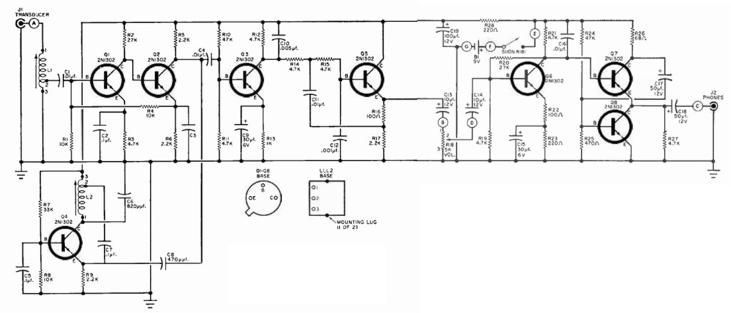
The Ultrasonic Sniffer circuitry consists of seven transistor stages with all parts mounted on a printed circuit board, except jacks J1 and J2, and volume control R18. Circled letters indicate terminal points on the printed circuit board that connect to circuit components mounted on the cabinet. Click the image above for a larger, printable version of the schematic.
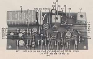
Only those parts specified in the Parts List or exact replacements with the same physical size should be mounted on the printed -circuit board. Any odd replacement parts may make wiring unit difficult.
When the transducer is plugged into jack J1, it forms a tuned circuit with coil L1. The circuit, analogous to a radio set’s r.f. tuning coil and capacitor, resonates between about 37.5 and 42.5 kc. All sounds that the transducer picks up within this range are passed along to transistor Q1. Transistors Q1 and Q2, equivalent to the r.f. amplifiers of our hypothetical superhet receiver, amplify the 37.5 – 42.5 kc. ultrasonic signals.
Oscillator Q4 provides a 37.5-kc. signal which is coupled to the base of mixer Q3 along with the 37.5 – 42.5 kc. signals from Q2. These signals combine in the mixer to generate “difference” frequencies between 0 and 5 kc. Capacitor C10 partially filters the “sum” frequencies from the output of Q3, but it leaves the 0 – 5 kc. “difference” frequencies virtually untouched.
The “difference” frequencies retain the basic “sound pattern” of the original, inaudible, ultrasonic signals. They lie well within the normal audio range, however, and need only amplification to be heard. Here the analogy to a superhet breaks down, since the output of a superhet mixer is an i.f. signal which must be “detected” (to extract the original audio modulation) before it can be heard.
The output of Q3 is fed to Q5, which is connected as an “emitter follower.” Transistor Q5’s main function is to provide a proper impedance match between Q3 and volume control R18. It also acts as another filter, helping C10 to attenuate unwanted ultrasonic signals.
Audio signals from R18 feed transistor Q6, which is the audio amplifier. And the output of Q6 is fed to transistors Q7 and Q8, which form an “augmented emitter follower.” Their output, available at jack J2, will match a set of low-impedance headphones.
Power for the circuit is supplied by 9-volt battery B1, and controlled by switch S1.
Parts List
- B1—9-volt battery (Burgess 2MN6 or equivalent)
- C1, C4, C11, C16—0.01-μf., 150-volt ceramic disc capacitor (Centralab DM-103 or equivalent)
- C2, C5, C7—0.1-μf., 10-volt ceramic disc capacitor (Centralab UK10-104 or equivalent)
- C3—2-μf., 6-volt electrolytic capacitor (Lafayette CF -161 or equivalent)
- C6—820-μμf., 300-volt silvered-mica capacitor (Elmenco DM -15-681J or equivalent)
- C8—470-μμf., 1000-volt ceramic disc capacitor (Centralab DD -471 or equivalent)
- C9, C15—30-μf., 6-w.v.d.c. subminiature electrolytic capacitor (Lafayette CF-167 or equivalent)
- C10—0.005-μf., 150 -volt ceramic disc capacitor (Centralab DD-M502 or equivalent)
- C12—0.001-μf., 1000-volt ceramic disc capacitor (Centralab DD-102 or equivalent)
- C13, C14—10-μf., 12-w.v.d.c. subminiature electrolytic capacitor (Lafayette CF-173 or equivalent)
- C17, C18—50-μf., 12-w.v.d.c. subminiature electrolytic capacitor (Lafayette CF-176 or equivalent)
- C19—100-μf., 12-w.v.d.c. subminiature electrolytic capacitor (Lafayette CF-177 or equivalent)
- J1—Shielded phono plug (Lafayette MS-593 or equivalent)
- J2—Phone jack to match plug on headset
- L1, L2—Special ultrasonic coil (Admiral 69C251-1-A)*
- Q1, Q2, Q3, Q4, Q5, Q6, Q7, Q8—2N1302 transistor (Texas Instruments, G.E.)
- R1, R4, R8—10,000 ohms
- R2, R2—27,000 ohms
- R3, R11, R12, R14, R15, R19, R21, R27—4700 ohms
- R5, R6, R9, R17—2200 ohms
- R7—33,000 ohms**
- R10, R24—47,000 ohms**
- R13—1000 ohms**
- R16, R22—100 ohms**
- R18—5000-ohm potentiometer, audio -taper (with s.p.s.t. switch S1)
- R23, R28—220 ohms
- R25—470 ohms
- R26—68 ohms
- S1—S.p.s.t. switch (on R18)
- 1¼” x 3″ x 2-1/8″ aluminum utility box (Bud CU-2106-A or equivalent)
- 1—Special printed -circuit board*
- 1—Ultrasonic transducer (Admiral78B147-1-G)*
- 1—100-to-1000 ohm headset (Telex HFX-91 or equivalent)
- —1¼” spacers, battery connector, knob, wire, solder, etc.
*The coils, printed-circuit board, and transducer are available from Daniel Meyer [address deleted] for a total of $10.00, postpaid.
** All resistors ½-watt, 10%, unless otherwise specified.
Construction
Building the Ultrasonic Sniffer is a relatively simple job, thanks to the availability of a specially-etched circuit board (see Parts List). All holes in the printed board should be drilled with a No. 60 drill from the copper side of the board. The holes for L1 and L2 will have to be drilled with a slightly larger size drill since the lugs on these parts are larger than the leads on the other components.
Because of the critical space limitations on the board, the Parts List gives rather complete specifications for all capacitors. Try to pick up the exact units listed—but if you can’t, be sure that whatever you do buy will fit. Keep in mind that the voltage ratings for the electrolytics are fairly critical, but anything over ten volts will do for the other capacitors.
There should be no problems in hooking up the components. The transistors and coils will only fit one way, and, with the exception of the electrolytics, there are no polarities to worry about. Polarities for each electrolytic capacitor must be carefully checked before you solder them in place.
Use only rosin core solder when soldering components to the board. “Ersin” 60/40 is recommended and available from most radio supply stores. As a soldering aid, buff the board lightly with fine steel wool until the copper is bright and shiny; do this before inserting the components. Battery B1 is fastened in place by means of a piece of hookup wire. Pass the wire around B1 and through a couple of holes drilled in the board; then tie the ends of the wire together. The battery leads are wired to the board at points F and G (see schematic diagram) . The remainder of the construction is relatively easy. Potentiometer R18 and jacks J1 and J2 are mounted on a 5 1/4″ x 3″ x 2 1/8″ aluminum utility box. The board is held in place in the box by means of four 1 1/4″ spacers. These are installed at the corners of the box top and placed to mate with the mounting holes in the board.
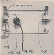
Parts mounted on chassis cover are prewired with extra-long leads. Circled letters indicate connection points so indicated on schematic diagram.
Run the “hot” leads from J1 and J2 to points A and C on the board, respectively. Potentiometer R18’s arm is wired to D; the “high” end of R18 goes to B; and switch S1’s terminals run to E and F. Finally, solder the ground lead (from the “frame” terminal of J2 and the “low” end of R18) to the ground bus which circles the board at its edges. Complete the construction by running a bead of solder around one of the 1 1/4″ spacers where it touches the ground bus. This will ensure good contact between the board and the box.
Adjustment
Before closing up the utility box, you must adjust coils L1 and L2. For this task, you’ll need a signal generator that can be tuned up to 38 kc. Begin by plugging a headset of 400 ohms impedance or higher into J2, and the input transducer (microphone) into J1. This is important, as the tuning of L1 is affected by the transducer. Turn switch S1 on, and set potentiometer R18 to about the middle of its travel. Set the signal generator to 37.5 kc., turn the generator output control to minimum, and loosely couple the output lead to the insulated wire connecting J1’s center contact to L1. You can do this by looping two or three turns of the generator output lead around the J1 -L1 lead wire. Now turn up the generator output control until a tone is heard in the phones, and adjust the slug of coil L2 until the tone “zero beats.” Next, retune the generator to 38 kc., producing a 500 -cps tone in the phones. Adjust the slug of L1 for maximum headphone volume, reducing the generator output as necessary to avoid overloading. Remove the generator lead from the J1 -L1 lead, install the chassis cover, and the Ultrasonic Sniffer is ready.
Operation and Applications
Don’t expect to be overwhelmed with sound as soon as you turn the unit on. Though there are many ultrasonic sounds to be heard, these high frequencies are easily blocked and absorbed. Furthermore, the transducer element is quite directional. A good test for proper operation is to rub your fingers together (lightly) at arm’s length from the transducer. With R18 set at maximum, you should be able to hear the sound clearly. Now have someone jingle a bunch of keys from 10 to 15 feet away; this sound, too, should be clearly heard.
Insect and animal life provides a fascinating source of ultrasonic sound. Take the unit out to a wooded area some evening and probe around the trees and bushes. You should be rewarded with ultrasonic “signals” from tree locusts, tree frogs, and other wildlife.
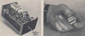
After unit is wired (left, above), close up chassis box to protect parts, then connect microphone (right) to jack J1, plug in headset, and advance volume control until a rushing sound is heard.
If you happen to live in an area where bats are common, you’ll be able to hear the pulses these animals send out to find their way or locate food. They begin at about 100 kc., then shift downward to about 20 kc., and can be detected as they pass through the sensitive range of the transducer. On a more practical level, gases escaping under pressure generate high intensities of ultrasonic sound. For this reason, the Sniffer makes an excellent “leak detector.” It can be used, for example, to check auto exhaust systems for tightness. The author has even employed the unit to set valve tappets on his car. Since the microphone is very directional, it can be aimed to hear sounds from one valve only. The tappet-adjusting nut is turned (while the engine is running) until no clicks are heard.
One last tip: the instrument is an excellent tool for testing ultrasonic remote-control transmitters for TV sets. Each control button should produce a tone, and all tones should be of about the same magnitude. With a little experience, you’ll be able to spot malfunctions quickly.
About the Author
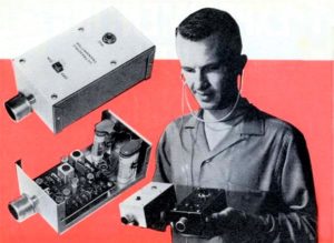 Daniel Meyer (February 6, 1932 – May 16, 1998) was the founder and president Southwest Technical Products Corporation. He earned a bachelor’s degree in mathematics and physics in 1957 from Southwest Texas State, and became a research engineer in the electrical engineering department of Southwest Research Institute.
He soon started writing hobbyist articles. The first was in Electronics World (May 1960) and later he had a two part cover feature for Radio-Electronics (October, November 1962). The March 1963 issue of Popular Electronics featured his ultrasonic listening device on the cover (featured here). The projects would often require a printed circuit board or specialized components that were not available at the local electronics parts store (by design!), but readers could purchase them directly from Dan Meyer.
Dan Meyer saw the business opportunity in providing circuit boards and parts for the Popular Electronics projects. In January 1964 he left Southwest Research Institute to start an electronics kit company. He continued to write articles and ran the mail order kit business from his home garage in San Antonio, Texas.


