As an engineer and amateur guitar player, I was looking for a device that allowed me to design my own sound effects and combine them, at a reasonable price. There are a number of amazing pedals and pedalboards out there; their prices are fair, and I would certainly like to have them all. But I also have some unique sound ideas that I wanted to develop, and so building my own pedal seemed the best path for opening up those new possibilities. POP—the Programmable Open Pedal—is the result of that continuing effort.
POP is, for all practical purposes, a generic digital effects pedal. Like any pedal, you plug your guitar into the input and connect it to an amp (or other pedal input), producing a sound that has been modified according to the programmed settings on the unit. In another sense, the pedal is a complete computing system housed inside a pedal-sized box—a computer you can connect to, configure, and program at your pleasure, hence, the Programmable in POP. (When I say programmable, I mean programmable in the sense of computer programming: choose your favourite programming language to develop the pedal in any way you like.) Finally, POP is “open” because all technologies it employs are open source, from the computer board itself to the last piece of software.
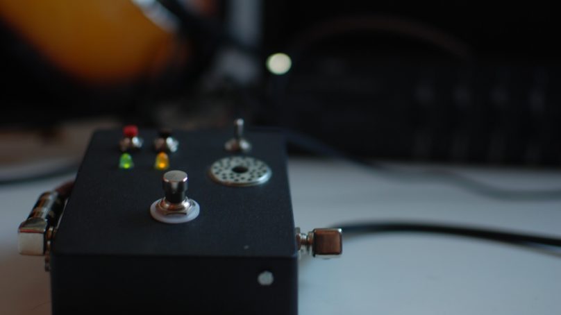
With that, let’s begin with an orientation on the pedal’s external aspect, buttons, and connectors:
![]()
- Input: The standard ¼” input jack for your guitar, the output of another pedal, or even a microphone.
- Output: There are two jacks for output because it is a stereo pedal. Depending on the effect, right and left channels can do different things, as we’ll see later. The right output is geometrically aligned with the input jack. Plug your mono amplifier (or another pedal) into the right channel, and maybe another amplifier or effects pedal into the left channel.
- Footswitch: Push it with your foot and your guitar signal will go through the effects unit. Push it again and the signal will go directly from the input to the output without modification, making it a “true bypass” pedal. Because the input is mono and output is stereo, only one channel (right) will be connected to the input in bypass mode, and the other (left) will keep connected in both modes.
- Yellow LED: It lights when in effect mode (signal is processed by the pedal) and is off when in bypass mode.
- Green LED: It lights when the unit is ready, and also blinks and shuts temporarily to communicate with you.
- Red button: This is the shutdown/reset button. Press it until the green LED switches off, and the unit will shut down. Press it for a couple of seconds and it will reset. In the latter case, the green LED will switch off and light again a moment later when the unit is ready.
- Black button: This is a user programmable button that can be used to trigger several actions.
- The hole: You don’t have to do anything with it, but it is interesting to know why it is there. The hole has two functions: 1) there is a fan below for cooling the unit, and 2) wireless waves can travel through it almost freely. It is approximately 20mm in diameter.
- Three-position mode switch: This controls three user programmable modes. As a convention, if you turn on the device with the switch in the lower position, a “maintenance mode” is activated, in which wireless, Bluetooth, and network services are on. Apart from that, you can also have an effect programmed in maintenance mode. If you change the position of the switch with the device on, the green LED turns off momentarily, until the new mode is active.
- Power supply plug: You can connect a 9V power supply. The connector must have ground in the centre ping, with the outer collar positive, as those typically used for guitar pedals. It should supply at least 400mA, so use a good regulated power supply. If the unit is off, plug a power supply in here to turn it on. It has a battery inside, so if you unplug the unit without shutting down, there is still time to press the red button. It can even work without being plugged in for an hour or so.
- Hard reset button: This little black button shouldn’t be used often. Has two functions: if the unit is off and you don’t want to plug it in, hold it for one second and the unit will turn on (no magic, there is a battery inside). If the unit was on and doesn’t respond and you need to reset it or turn it off, hold the button for 10 seconds, and it will turn off. Avoid this last action as much as possible, as it could damage the unit in the long term. It is always better to try to connect to it through any means or simply wait a while until it responds again.
- Type A USB connector: Its main purpose is to connect a MIDI controller here in order to modify effects parameters on the fly. But you can connect anything to it, from a storage device to a mouse. Be careful with the current consumption of the connected device. If it exceeds 100mA, you should use a powered USB hub.
- MicroUSB connector: when a wireless network is unavailable, or the unit does not respond, or you have to reinstall all its software again, this connector acts as an emulated serial port, so you can connect to a serial console and get right into the belly of the device. It will be necessary to connect via this port in order to also configure wireless access.
Now a couple of online videos to provide a taste what can be done with the device:
Video 1: Unit general demo:
Video 2: Autoovation demo:
Getting Inside
Now let’s check out the internals of the unit, see how it works, and review the primary components.
Computer: C.H.I.P. board from Next Thing Co (NTC), based on Allwinner R8 SoC. This board is really tiny, very cheap, $9, and has everything you will need to build a basic DSP computer and more: audio card with 44.1/48/96/192 KHz, 24 bits, stereo output, mono input. And more: integrated wireless LAN, Bluetooth, USB, general-purpose input/output pins. You can learn more about this at https://getchip.com/
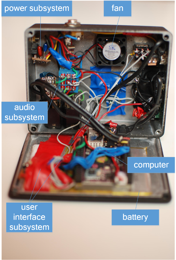
Battery: A general purpose 3.8 V 2800mAh battery that fits in the box.
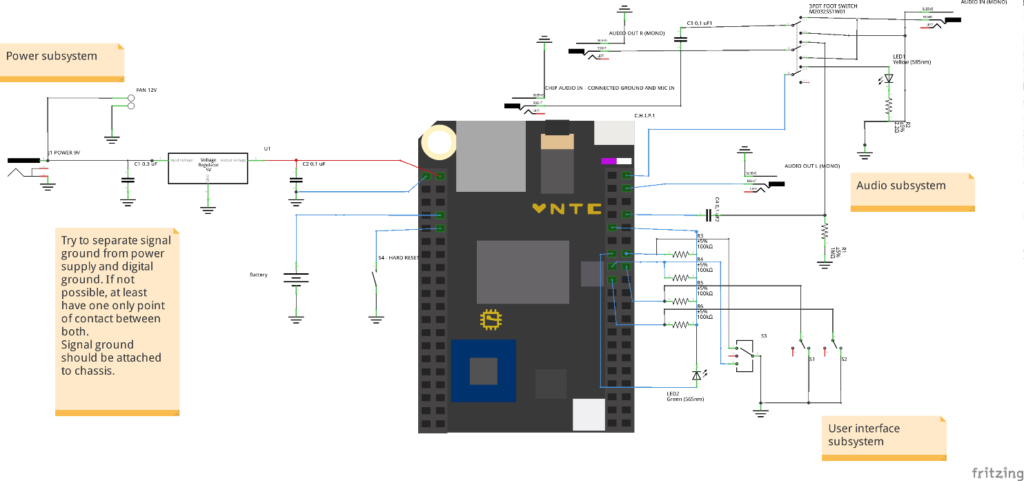
Power subsystem: A 2.1mm chassis socket connector, and a voltage regulator that converts the 9V input into 5V for powering the computer.
Fan: 12V tiny 25mm fan connected to 9V that keeps everything cool, never exceeding 55ºC. Without it, the computer temperature will reaches 75ºC.
User interface circuit: This circuit connects the buttons, switch, and green LED to the general purpose I/O connector of C.H.I.P. board. The resistors in this circuit are pull-up resistors that, being connected to 3.3V, define the state of the digital inputs when not connected to ground through the buttons and switch. According to C.H.I.P. documentation, they are not needed, but I prefer to keep the whole system prepared for any computer board that fits inside the box, maybe a new C.H.I.P. release or a Raspberry Pi that is able to capture audio, or a dedicated DSP board.
The three-position switch acts as a two-bit selector for board GPIO pins 1 and 2. When in the lower position, bit 1 is on and bit 2 is off. When in upper position, bit 2 is on and bit 1 is on, and when in middle position, both bits are 0. The green LED is connected between 3V3 and pin 0, so when you send a 0, the LED receives a voltage and lights. Pins 3 and 4 are connected to red and black buttons, respectively. Buttons are on in the default state and off when pressed. When a button is pressed, the corresponding bit is 1 because it is disconnected from ground. Table 1 summarizes the functions.
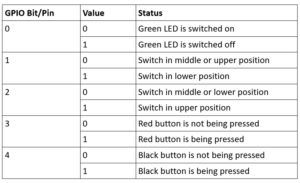
Table 1. GPIO Switch Settings.
Audio subsystem: This part of the unit comprises a 3PDT footswitch and all the circuitry needed to avoid noise when switching from bypass to through-board audio. When bypass is selected, the input jack is connected directly to the right output. When through-board is selected, the input jack is connected to the board audio capture jack, and the right output to the board right audio output. Left audio output is always connected to the board left audio output. The 3PDT footswitch also switches on and off the yellow LED.
Build it Yourself
Alright, if you’re ready to build this unit, Table 2 details the bill of materials.
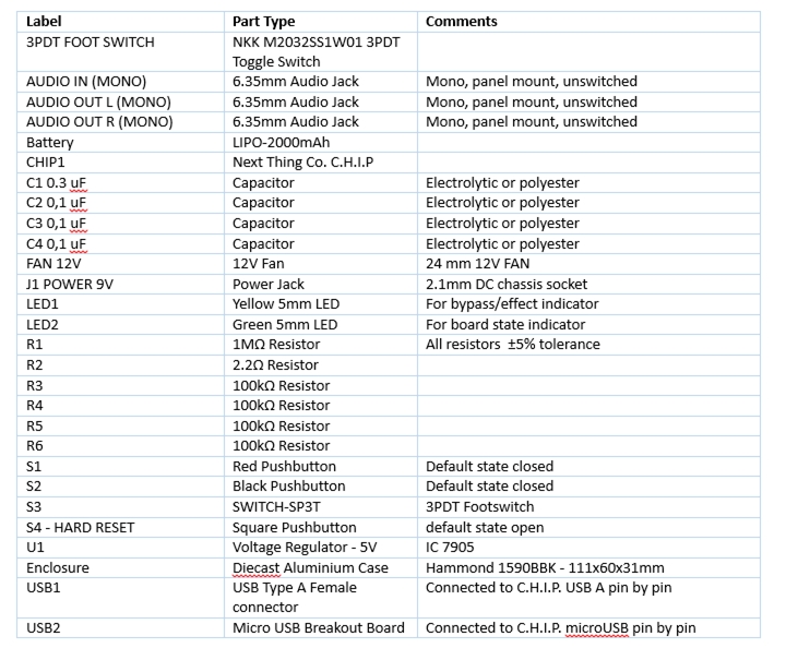
Table 2. Bill of Materials.
Recommended online shopping sites include:
- For electronic components and enclosure, check https://www.bitsbox.co.uk/.
- For the C.H.I.P. board, go to https://getchip.com
The unit is not very complex, so the building process should be fairly straightforward. Moreover, my design is certainly subject to many changes. In any case, here are a few tips that will prove useful:
- For robustness, connect the audio output to the right header audio outputs of C.H.I.P., pins labelled HPR, HPL and HPCOM, not to the mini jack connector.
- Do connect the audio input and signal ground to the mini jack input, because it has additional filtering circuitry inside the board that is not present when connecting to header pin MICIN1. In order to capture audio with the mini jack connector, it is necessary to cut a circuit trace, as explained here: http://docs.getchip.com/chip.html#microphone-and-audio-input
- For the 3PDT switch, do not connect tags without any electronic components, as they usually do in most pedal clone schematics. Use my circuit above, or even better, improve it and send it to me!
- Do not feed the board using its microUSB connector, but through PIN U13 (CHG-IN) in left header, as described here: https://bbs.nextthing.co/t/chip-power-pins-maximum-current/7164/9. Otherwise you will kill your board when connecting a MIDI controller and the battery will not charge fast enough.
- Place a voltage regulator as far as possible from board, so you don’t toast it.
- Put the enclosure hole on top of the board right where the wireless antenna is located, as you indicated in the pictures.
- Grounding: try to separate signal ground from power ground, or at least have one only point of contact between them, avoiding “ground loops”.
- Shielded wires: using shielded cables for signal inside the pedal is usually recommended but not mandatory, as the enclosure acts as an electromagnetic isolator. But in this case you have an open computer emitting radio waves inside a metal box, so it is a good idea to isolate signal cables with shields. You could also isolate the computer, but in that case you wouldn’t have wireless networking and Bluetooth.
Software Stack
The computer board is flashed with C.H.I.P. NTC OS version 4.3. This is a specific Debian Linux distribution for this board. There is a 4.4 version, but I had some problems with audio capture and preferred to stick with version 4.3.
JACK2 audio system is the most important software piece needed to run the unit. For a headless system like POP, JACK2 will have to be compiled specifically with some options, I will give some directions in the next section.
The audio effects are modelled as LV2 plugins, and are available from multiple sites on the Internet. (LV2 is an acronym for Linux Audio Developer’s SimplePlugin API (LADSPA) version 2, an open standard for audio plug-ins and matching host applications.) See the LV2 references toward the end of this article for more information. These plugins have to run on a host software, like guitarix or mod-host. In my case, I ended up using mod-host for ease of use and stability. Also tried rakarrack but it was very unstable on this platform—really a pity, because it was my first option.
In order to interact with the unit, some scripts have to be written. The complete code listing can be found in Appendix A, and they are:
pop_init.sh: This script is run when the system starts up and configures the mode according to the switch position and also launches more scripts. When the switch is not in a lower position, it deactivates the wireless network and Bluetooth.
pop_loop.sh: This script is launched in background and responds to changes in switch position and button presses. When the red button is pressed, it resets or shuts down the unit, depending on how long it is held. The black button can have many uses. In this example, it launches the autoovation effect that you can see in the video, linked above.
pop_p1.sh, pop_p2.sh and pop_mnt.sh: These scripts are launched when the switch is in the upper, middle, or lower position, respectively, and launches the corresponding jackd configuration and effects of your choice.
led_on.sh and led_off.sh: These scripts shut on and off the green LED.
In order to compile jackd, and have mod-host and LV2 effects compiled and working, you will need to install many packages from the C.H.I.P. repository, or even from other sites. Visit Appendix C for a list of installed packages.
Autoovation is made by detecting audio activity in input, then waiting for silence, and playing a file randomly from a list of mp3 recorded ovations. For audio detection, silentjack (https://www.aelius.com/njh/silentjack/) was used (thanks to Nicholas J Humfrey for his work and for allowing me add a feature to his code). You can find the code for this feature in Appendix A.
Compiling Jack2
Compiling a jack for a headless system (a system with no graphics) is fairly easy via cross compiling or right from the C.H.I.P. itself, if you don’t mind the wait. Complete information about how to do it can be found here: https://capocasa.net/jackd-headless
mod-host
mod-host is a piece of software that can run a LV2 plugin without need of any other graphical software like guitarix, making it ideal for a headless system. Source code and instructions to make it work can be found here:
https://github.com/moddevices/mod-host
This software comes from MOD (https://moddevices.com/) and is freely available. MOD project is amazing, like POP on steroids. I discovered it after starting the POP project, and they are very similar in concept, but MOD is a high-quality commercial product. More information can be found at https://www.kickstarter.com/projects/modduo/mod-duo-the-limitless-multi-effects-pedal
LV2 plugins
There are hundreds of LV2 plugins out there. You can even use the ones that come with guitarix, or explore several websites, including https://github.com/moddevices/, the one for MOD software. You can even install invada LV2 plugins from the C.H.I.P. repository with apt-get or aptitude.
First thing to do is to download, compile, and install lv2 and lilv:
lv2: http://lv2plug.in/
lilv: http://drobilla.net/software/lilv
After that, you will have access to two very useful tools:
- lv2ls: lists all lv2 plugins you have installed
- lv2info: gives information about a particular lv2 plugin.
Dependencies for lilv can be found in http://drobilla.net/pages/software.html.
LV2 plugins can be controlled using a standard MIDI controller. Parameters for a particular plugin are displayed by running lv2info, like the following:
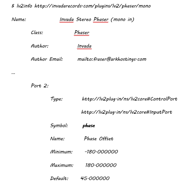
The phase parameter can be controlled by a certain MIDI controller knob of your choice. In my case, I use mod-host this way: from a shell script, I launch mod-host:
echo load commands_$1.txt | mod-host -i
In $1 I pass the name of the plugin. Previously I have prepared a commands file like this one:
$ cat commands_leslie.txt
add http://drobilla.net/plugins/mda/Leslie 0
connect system:capture_1 effect_0:right_in
connect midi_controller:capture mod-host:midi_in
connect effect_0:right_out mod-host:monitor-in_1
param_set 0 mode 1
param_set 0 lo_width 0.8
param_set 0 speed 0.8
midi_map 0 speed 0 16 0 1
The keywords add, connect, param_set and midi_map are mod-host commands; you can execute “man mod-host” to understand all the commands and options. In the code above, a Leslie effect is loaded, its input connected to jack2 capture port, its output is connected to mod-host “monitor-in” port, and the connected MIDI controller is connected to mod-host MIDI port. After that, several parameters are set, and finally parameter speed is associated with the knob numbered 16 in MIDI port 0. All parameters and their values for a LV2 plugin can be found by executing lv2info, as I mentioned before.
Alternatives
Choosing JACK2 and LV2 plugins is just one option. You can go another way and choose JACK2 + guitarix, for example, for a good user interface when configuring the unit (don’t forget to make a ssh -X in order to have Xwindow forwarding). Guitarix can be launched with -nogui option as well, so it works in headless mode. You can also use rakarrack; I hope the problems I encountered will be solved sometime soon. Rakarrack and guitarix each have their advocates and detractors. They both are good pieces of software, but Guitarix is focused on amplifier and cabinet modelling, while rakarrack functions more like a pedalboard simulator.
You can also combine Supercollider and JACK2 and program your own original effects. You will need time if (like me) you are not an expert in Supercollider; it is a complete programming language in its own right.
Another alternative similar to Supercollider is Pure Data, which has a very active community and a graphical user interface to create and combine effects.
Battling Latency
Latency is one of the main pains when working with DSP. Latency is comprised of several sub-latencies, some of which are beyond your control, e.g., the latencies introduced by cables, connectors, and DSP hardware. But the biggest offender is the software itself, and that is something over which you do have some control. When you launch JACK2 daemon (jackd), some parameters can control latency. For example, frames per period and periods per buffer give the total amount of bytes that have to be processed by JACK2, thus determining the time needed to process the digitalized audio. Sampling frequency (48KHz or 44.1KHz usually) also enters the equation.
But reducing latency by raising sampling frequency or lowering buffer size has a side effect: if the CPU is not fast enough, it is not able to do its processing from one callback to the next one, because they are invoked too often. The result is popping and clipping and noises that yield a very bad audio quality.
On the other hand, configuring a higher latency is annoying for the player and the audience, because it can be noticeable. A latency over 20ms is long enough to be perceived. In my case, I ended up choosing these parameters:
- Frames/period: 256
- Periods/buffer: 3
- Sampling rate: 48KHz
It results in a software latency of 16ms, almost imperceptible, and well-suited to C.H.I.P. speed.
Kernel Modules for the MIDI Controller
Another obstacle I found, is that the MIDI controller didn’t work out of the box with C.H.I.P. OS 4.3. I had to compile several kernel modules and load them instead of the ones that came with the distribution, and also add some kernel modules that didn’t come with the default kernel. In order to keep things simple, and not modifying the OS too much, I put the modules in the home directory of the user that launches the jackd and effects software. The startup scripts load them from there.
Compiling the kernel modules is beyond the scope of this article. Suffice to say that you will need the following modules compiled together from C.H.I.P. OS 4.3 kernel source code:
- snd-seq-device.ko
- snd-seq.ko
- snd-rawmidi.ko
- snd-seq-midi-event.ko
- snd-seq-midi.ko
- snd-usbmidi-lib.ko
- snd-usb-audio.ko
I can provide the binaries already compiled for C.H.I.P. OS 4.3.
Project History
Last year, after buying a pair of quite good digital pedals, I wondered if it would be possible to build a complete, stompbox-sized guitar pedal powered by a development board like Raspberry Pi. I love Raspberry Pi, but it had two main problems:
- Size: It is quite big for fitting into a typical enclosure.
- Audio capture: It does not capture audio (even version 3), unless you install an external audio card. Forget USB audio cards, because they don’t have DMA, and consequently, audio capture is too slow. With an audio card on top, the size problem only gets worse.
After moving on from Raspberry Pi, I explored several specialized DSP cards, but they were too expensive or too big. As part of my research, I found an interesting project here:
https://sites.google.com/site/nextaudiodsp/
This is a DSP board based on AL3102 IC. Very interesting, because specialized boards tend to give the best results in terms of audio quality, but it was too limited for my purposes.
Late in 2015 I learned about C.H.I.P., a new board that had everything I needed for $9: WiFi, Bluetooth, audio capture. Plus, it was tiny, battery friendly, and had general purpose ports. But I had to wait until June, 2016 to get my hands on it. In the meantime, I began to design the pedal anyway.
When I received the board, the first thing I did was a proof of concept, without soldering anything, just to test the speed of the CPU (1GHz) and the quality of the SoC DSP C.H.I.P. The results were quite good, enough for my purposes and better than expected, so I went on constructing the unit.
From the software perspective my first attempt was to remove the kernel module and program the hardware myself. The idea was to be as fast and real-time as possible. I still keep some software from that phase, and I learned a lot about the audio hardware and DSP, but it was too labour-intensive. When I found myself building a sound driver, I stopped reinventing the wheel and took another path: standard open source software made by the community. With this new approach I would have a huge amount of already tested software, and a resulting device that was easier to maintain and evolve.
I started with JACK2 and guitarix/rakarrack. Rakarrack was rather unstable in this platform, and was soon abandoned. Guitarix gave better results, but had some problems:
- Memory consumption, even in –nogui mode.
- In order to configure it, I needed to launch a user interface through ssh forwarding, and it was not very agile.
Another technology I tested was Supercollider, as it gave me complete freedom to configure, program, and do whatever else from an ssh text session. The results were not bad, but learning Supercollider is not easy. I have not abandoned completely the idea, but I wanted some results, so I kept on looking for something in the middle of the guitarix-Supercollider continuum.
My last and definitive attempt up to now was LV2 plugins launched without a user interface with mod-host from the MOD project. It provides the benefits of having already tested hundreds of effects, but without giving up the option of creating your own effects, as you can also program your own LV2 plugins.
From a hardware perspective, if you are used to building pedal clones, building POP is not difficult. My main problems were related with temperature and grounding.
Temperature inside the box was too high at the beginning with the device plugged in; I had to change the initial voltage regulator position and install a small fan. With the fan running, temperature was lowered from 75ºC to 55ºC, quite acceptable for this board.
Grounding with digital boards has some challenges. You have to be aware of the different types of grounds that an electronic circuit can have. Signal ground is not the same as power ground and chassis ground. But in “real life,” they usually have to be interconnected. If this is the case, they have to be connected only through one point, otherwise you can have a ground loop, which translates into computing and power line noise. After re-examining my device interconnections I removed all those annoying noises.
For capturing audio using the mini jack connector, you have to cut a trace in the board and solder a new one (scary, yes). You can see the result in the picture at right.
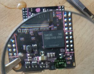
The process is very well explained here: http://docs.getchip.com/chip.html#microphone-and-audio-input
Future Improvements
This pedal can be considered POP V1. For future releases, I have some improvements in mind, and any other new features you might suggest will be most welcome:
- Additional footswitches, momentary or latching, that can be connected to GPIO ports, or create an internal MIDI controller with a board like Teensy.
- An expression pedal, connected to the AD converter on the C.H.I.P., or as a MIDI controller using Teensy.
- A faster board, or allowing more than one board to be used.
- A little display, for friendly user interfacing.
- Auto backing track by detecting chords and tempo, like they do in Digitech TRIO pedals.
- Communicating with the pedal through Bluetooth. A mobile application could interface with the pedal for easier manipulation of effects and modes of operation. An alternative could be to emit a modulated audible signal from the phone and to capture it through guitar pickups, similar to TC Electronic Toneprint technology.
References
Code
The complete code listing is available here as a Word document.
Hardware Links
http://bitsbox.co.uk (my favorite online electronics shop, since I am based in Europe)
LV2 Plugins
https://github.com/brunogola/mda-lv2
http://abgate.sourceforge.net/
https://github.com/moddevices/tap-lv2
https://github.com/moddevices/mod-lv2-data
https://github.com/moddevices/caps-lv2
https://github.com/moddevices/
https://github.com/zynthian/zynthian-plugins
https://github.com/DISTRHO/DPF-Plugins
https://github.com/DISTRHO/DISTRHO-Ports
https://github.com/SpotlightKid/mda-lv2
Linux Audio
http://www.audiosynth.com/ (Supercollider)
Installed Packages
After flashing C.H.I.P. with C.H.I.P. OS 4.3 or 4.4, you will need many packages for compiling jackd, mod-host and lv2 plugins, the list is quite large for this article. I recommend to read carefully the README or INSTALL files and websites of all projects. For some LV2 plugins, waf tool is used and for some others you will need premake3. I you need it, I can provide the complete list of packages installed in my POP unit (over 600 individual deb packages) and I can also give some support in compiling individual tools and plugins.
Interesting Related Projects
http://blog.zynthian.org/index.php/2015/11/22/building-a-zynthian-box/
My Personal Blog
Credits
Engineer and player: Manuel Guerrero – [email protected]
Pictures and general support: Inmaculada Méndez
